9. Appendix
9-5
4.
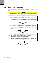
Control power supply: Supply single-phase AC 220 [V] to C1 and C2.
Be sure to check external input voltage before turning on the servo drive.
Check whether the display is normal. (There should be no break on the seven segments or
alarm output.)
5.
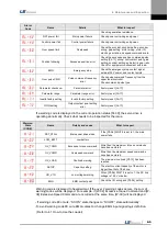
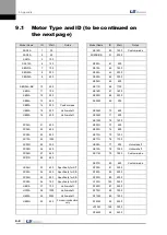
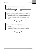
Motor ID setting: Set motor ID in the parameter [P0-00] and encoder pulse in the parameter [P0-
02] respectively. (Refer to "Appendix 1.")
(
※
The serial encoder is automatically set.)
Easy check: Check the motor ID and encoder pulse on the product name tag attached on the
right side of the motor.
Check whether the external control signal input is normal.
For information on how to handle the keys of the servo drive loader, refer to "4.1 Loader
Handling."
6.
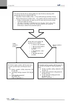
Main power supply: Supply three-phase AC 220 [V] to L1, L2, and L3.
Be sure to check external input voltage before turning on the servo drive.
When power is supplied, the red lamp on the charge LED at the bottom of the loader
window comes on.
If an alarm is displayed, it indicates that there is an error in the power circuit, wiring of the
servo motor, or encoder wiring.
Turn off power and fix the error using the information in "[Alarm Codes and Descriptions]."
Summary of Contents for L7 A001
Page 1: ...VER 1 5...
Page 2: ......
Page 32: ...1 Product Components and Signals 1 20...
Page 38: ...2 Installation 2 6...
Page 54: ......
Page 188: ...7 Product Specifications 7 26 L7 A020 L7 A035 Weight 2 5 kg cooling fan included...
Page 210: ...8 Maintenance and Inspection 8 14...
Page 211: ...9 Appendix 9 1 9 Appendix...
Page 218: ...9 Appendix 9 8...
Page 221: ......
Page 222: ......

