4. Parameters
4-62
(2)
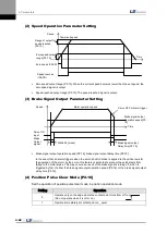
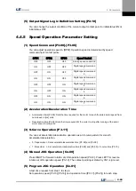
Speed Operation Parameter Setting
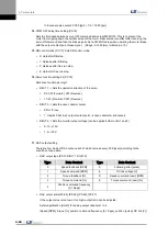
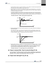
Zero speed output range [P2-12]: When the current speed becomes lower than the set speed, the
zero speed signal is output.
Speed-reached output range [P2-13]: The speed-reached signal is output.
(3)
Brake Signal Output Parameter Setting
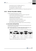
Brake signal output operation speed [P2-14], brake signal output delay time [P2-15]
In the event that an alarm triggers when the servo’s built-in brake is applied to the vertical axis for
the operation of the motor by the servo, this feature is activated to prevent the vertical axis from
falling to the motor brak
e. This may occur as a result of the brake signal’s turning off, which is
triggered by first of either the brake signal output operation speed [P2-14] or the brake signal output
delay time [P2-15].
(4)
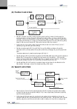
Position Pulse Clear Mode [P2-16]
Set the operation of position pulse clear mode in position operation mode.
Setting
Operation
0
Operate only on the edge where the contact point turns from off to on.
(Do not operate when it is off or on.)
1
Operate immediately at contact point on_ Level.
Motor operation speed
Speed
Servo ON
input
Brake
Output
signal
Within 50 [msec]
Brake signal output
Operation speed [P2-
14]
Time
Brake signal output
Delay time [P2-15]
Servo OFF or Alarm trigger
Speed
Command speed
Range of output for
speed reached
[P2-13]
Zero speed output
range [P2-12]
Zero speed (ZSPD)
Speed reached
(INSPD)
Time
Summary of Contents for L7 A001
Page 1: ...VER 1 5...
Page 2: ......
Page 32: ...1 Product Components and Signals 1 20...
Page 38: ...2 Installation 2 6...
Page 54: ......
Page 188: ...7 Product Specifications 7 26 L7 A020 L7 A035 Weight 2 5 kg cooling fan included...
Page 210: ...8 Maintenance and Inspection 8 14...
Page 211: ...9 Appendix 9 1 9 Appendix...
Page 218: ...9 Appendix 9 8...
Page 221: ......
Page 222: ......

