Chapter 8 Option Boards and Memory Module
XBC E-Type Main Unit
8-11
Ver. 1
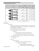
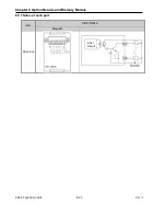
8.6.4 Interface with external devices
I/O
Internal circuit
Terminal
No.
Signal
O
per
at
ion
Input
guaranteed
voltage
1-phase
2-phase
Input
00
CH0
Pulse input
CH0
A-phase
input
On
20.4~28.8V
Off
6V or less
01
CH 1
Pulse input
CH0
B-phase
input
On
20.4~28.8V
Off
6V or less
02
CH 2
Pulse input
CH2
A-phase
input
On
20.4~28.8V
Off
6V or less
03
CH 3
Pulse input
CH0
B-phase
input
On
20.4~28.8V
Off
6V or less
COM
COM(Input common)
8.6.5 Function
1. Counter mode
a. High Speed counter module can count High Speed pulses which cannot be processed
by CPU module’s counter instructions (CTU, CTD, CTUD, etc.), up to binary value of 32
bits (-2,147,483,648 ~ 2,147,483,647).
b. Available input mode is 1-phase input or 2-phase input
c. Count increasing/decreasing methods are as follows;
i. 1-phase input :
I.
Increasing/decreasing count operation by program setting
II. Increasing/decreasing count operation by B-phase input signal
ii. 2-phase input : setting by difference in phase between A-phase and B-phase
d. Auxiliary modes are as follows
i. Count Latch
e. Input mode
i. 1-phase count mode
I.
Increasing/decreasing count operation by program setting
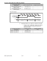
a. 1-phase 1-input 1-multiplication
i. A-phase input pulse is counted at rising and
increasing/decreasing will be decided by the program.
2.7 k
Ω
2.7 k
Ω
2.7 k
Ω
2.7 k
Ω
Summary of Contents for XBC-DN10E
Page 1: ......
Page 10: ...Table of Contents Table of Contents 6 10 10 CLEAR ALL PLC 29...

