


Learning Advanced Features
Adv
anc
ed
Feat
ur
es
245
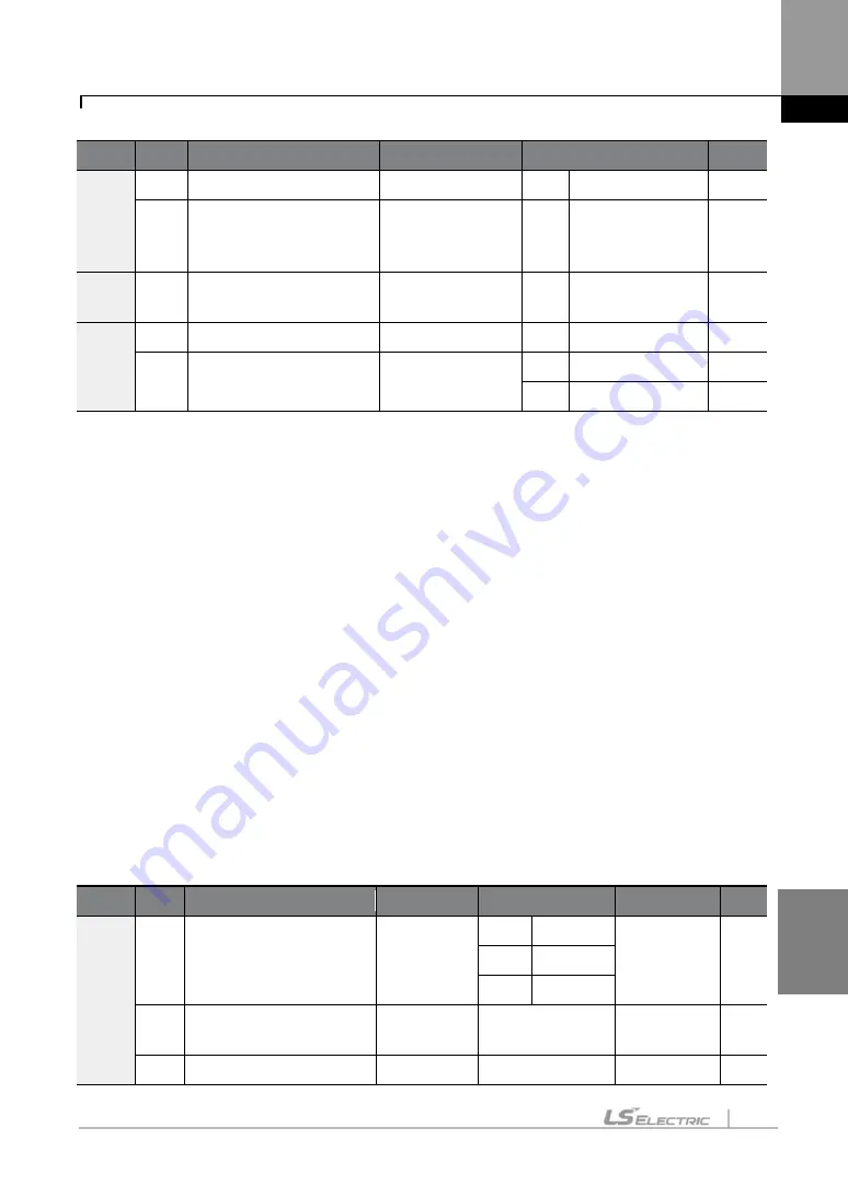
Group Code Name
LCD Display
Parameter Setting
Unit
acceleration time
69
Torque mode
–
speed
mode switching
deceleration time
SPD/TRQDec T
-
30.0
sec
IN
65
–
75
PX terminal setting
option
Px Define
35
Speed/Torque
-
DRV
09
Control mode
Control Mode
5
Vector
-
10
Torque control
Torque Control
0
No
-
1
Yes
-
Set a multi-function input Px to
“
35 (Speed/Torque)
”
.
If the terminal is on during a vector torque operation, where DRV-09 (Control Mode) is set to
“
5
(Vector)
”
and DRV-10 (Torque Control) is set to
“
1 (
Yes)”
, the operation switches from torque to
speed mode based on the acceleration and deceleration times set at CON-68 (SPD/TRQAcc T)
and CON-69 (SPD/TRQDec T).
If the terminal is on during a vector speed operation, where DRV-09 (Control Mode) is set to
“
5
(Vector)
”
and DRV-10 (Torque Control) is set to
“
0 (No
)”
, the operation switches from speed to
torque mode.
8.17
Kinetic Energy Buffering
When the input power supply is disconnected, the inverter’s DC link voltage decreases, and a
low voltage trip occurs, blocking the output. A kinetic energy buffering operation uses
regenerative energy generated by the motor during the blackout to maintain the DC link
voltage. This extends the time for a low voltage trip to occur after an instantaneous power
interruption.
Group Code Name
LCD Display
Parameter Setting Setting range Unit
CON
77
Kinetic energy buffering
selection
KEB Select
0
None
0
–
2
-
1
KEB-1
2
KEB-2
78
Kinetic energy buffering
start level
KEB Start
Lev
130
110
–
200
%
79
Kinetic energy buffering
KEB Stop
135
130
–
210
%
Summary of Contents for SV-iS7 Series
Page 17: ......
Page 114: ...Peripheral Devices 97 Group 2 ...
Page 115: ...Peripheral Devices 98 Group 3 ...
Page 116: ...Peripheral Devices 99 Group 4 ...
Page 159: ...Basic Functions 142 Code Description V1 Quantizing ...
Page 465: ...Safety Funtion STO Safe Torque Off 448 14 2 1 Safety Function Wiring Diagram ...


