


Basic Functions
180
Excessive torque boost will result in over-excitation and motor overheating.
7.14.2
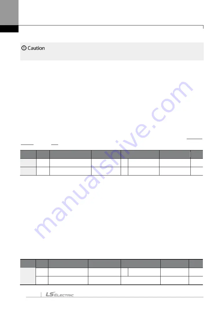
Auto Torque Boost
Set DRV-
15 to “
1 (Auto)
”
to enable auto torque boost. While manual torque boost adjusts the
inverter output based on the setting values, regardless of the type of load used during the
operation, auto torque boost enables the inverter to automatically calculate the amount of
output voltage required for the torque boost based on the entered motor parameters.
Because auto torque boost requires motor-related parameters, such as stator resistance,
inductance, and no-load current, auto tuning (BAS-20) has to be performed before the auto
torque boost can be configured. Similarly to manual torque boost, configure auto torque boost
while running a load that requires high starting torque, such as lift-type loads. Refer to
on page
Group Code Name
LCD Display
Parameter Setting Setting Range
Unit
DRV
15
Torque boost mode Torque Boost 1 Auto
0
–
2
-
BAS
20
Auto tuning
Auto Tuning
2 Rs+Lsigma
0
–
3
-
7.14.3
Advanced Auto Torque Boost
Manual Torque Boost, regardless of load characteristics, outputs the inverter voltage according
to the torque boost amount set by the user. Auto Torque Boost automatically calculates the
boost amount, but auto tuning the motor is required. For Advanced Auto Torque Boost, the
inverter outputs the inverter voltage by adjusting the boost amount according to the load itself
without auto tuning the motor.
Advanced Automatic Torque Boost is adjusted according to the load determined by the Adv
ATB M Gain, Adv ATB G Gain of DRV-27 and 28 values and it can be used when starting torque
is insufficient or when excessive current flows..
Group Code Name
LCD Display
Parameter Setting
Setting Range Unit
DRV
15
Torque boost mode Torque Boost
2 Advanced Auto 0
–
2
-
16
Fwd Boost
Note1)
Fwd Boost
2.0
0-15
%
Summary of Contents for SV-iS7 Series
Page 17: ......
Page 114: ...Peripheral Devices 97 Group 2 ...
Page 115: ...Peripheral Devices 98 Group 3 ...
Page 116: ...Peripheral Devices 99 Group 4 ...
Page 159: ...Basic Functions 142 Code Description V1 Quantizing ...
Page 465: ...Safety Funtion STO Safe Torque Off 448 14 2 1 Safety Function Wiring Diagram ...


