


251
Learning Advanced Features
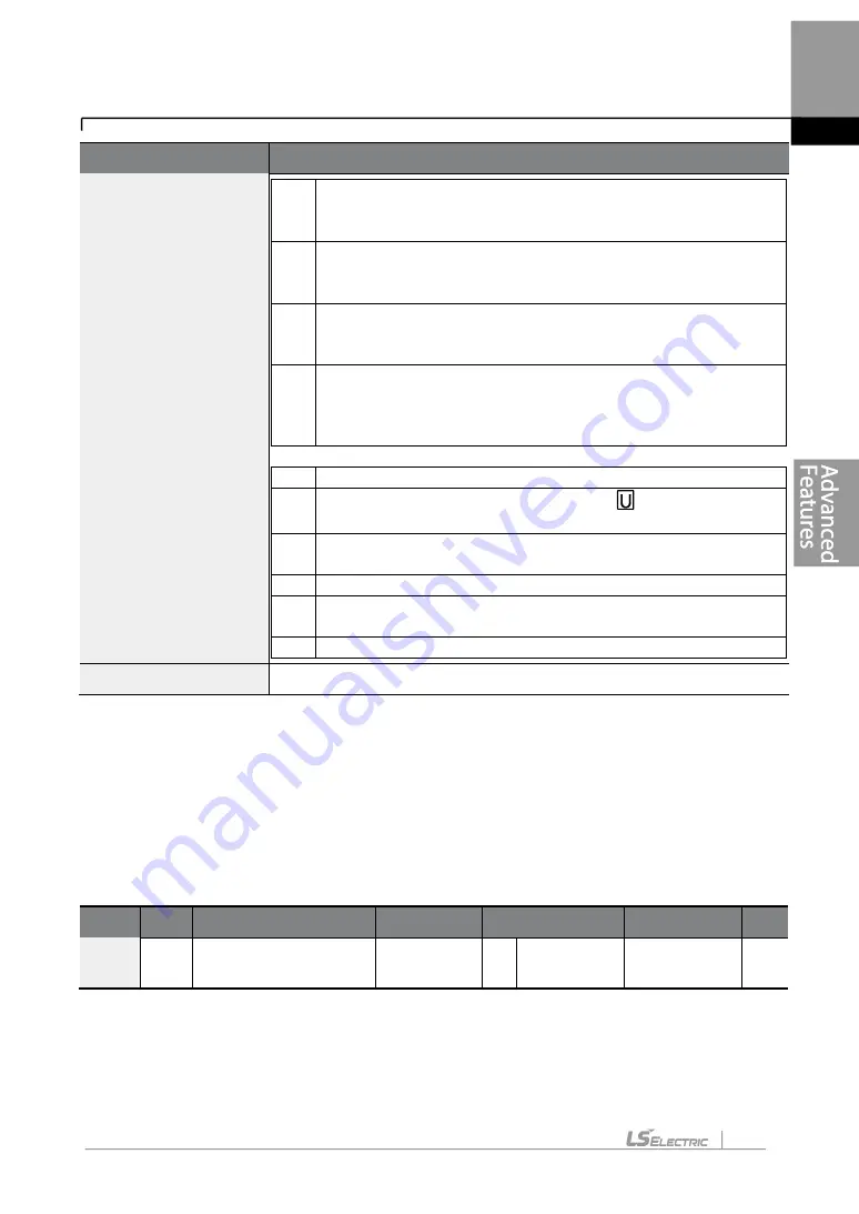
Code
Description
❹
Existing parameter registered as the user group code 40
❺
Setting range of the user group code.
Entering ‘0’ cancels
the settings.
3
❸
Set a code number
to use to register the parameter in the
user group. Select the code number and press the
[PROG/ENT] key.
4
Changing the value in
❸
will also change the value in
❹
.
If
no code is registered, ‘Empty Code’ will be displayed. Entering
‘0’ cancels the settings.
5
The registered parameters are listed in the user group in U&M
mode. You can register one parameter multiple times if
necessary. For example, a parameter can be registered as
code 2, code 11, and more in the user group.
Follow the procedures below to delete parameters in the user group
.
No. Settings
1
Set CNF-
42 to ‘3 (UserGrp SelKey)’. A
icon will be
displayed at the top of the LCD display.
2
In the USR group in U&M mode, move the cursor to the code
that is to be deleted.
3
Press the [MULTI] key
.
4
Move to ‘YES’ on the deletion confirmation screen, and press
the [PROG/ENT] key.
5
Deletion completed.
CNF-25 UserGrp AllDel
Set to ‘1 (Yes)’ to delete all registered parameters in the user group.
5.40 Easy Start On
Run Easy Start On to easily setup the basic motor parameters required to operate a motor
in a batch. Set CNF-61 (Easy Start On)
to ‘1 (Yes)’ to activate the feature, initialize all
parameters by setting CNF-
40 (Parameter Init) to ‘1 (All Grp)’, and restart the inverter to
activate Easy Start On.
Group Code Name
LCD Display Parameter Setting Setting Range Unit
CNF
61
Parameter easy start
settings
Easy Start
On
1
Yes
-
-
Summary of Contents for LSLV-H100 Series
Page 17: ...Preparing the Installation 4 37 90 kW 3 Phase ...
Page 18: ...Preparing the Installation 5 110 132 kW 3 Phase ...
Page 19: ...Preparing the Installation 6 160 185 kW 3 Phase ...
Page 20: ...Preparing the Installation 7 220 250 kW 3 Phase ...
Page 21: ...Preparing the Installation 8 315 400 kW 3 Phase ...
Page 22: ...Preparing the Installation 9 500 kW 3 Phase ...
Page 35: ...Installing the Inverter 22 ...
Page 50: ...37 Installing the Inverter Input and Output Control Terminal Block Wiring Diagram ...
Page 104: ...91 Learning Basic Features 0 10 V Input Voltage Setting Details V1 Quantizing ...
Page 181: ...168 Learning Advanced Features PID Command Block ...
Page 182: ...169 Learning Advanced Features ...
Page 183: ...170 Learning Advanced Features PID Feedback Block ...
Page 184: ...171 Learning Advanced Features PID Output Block ...
Page 185: ...172 Learning Advanced Features PID Output Mode Block ...
Page 198: ...185 Learning Advanced Features EPID1 Control block ...
Page 199: ...186 Learning Advanced Features EPID2 Control block ...
Page 220: ...207 Learning Advanced Features ...
Page 235: ...222 Learning Advanced Features The Time Chart for the Exception Day ...
Page 506: ...Table of Functions 493 ...
Page 520: ...Table of Functions 507 8 16 4 Cooling Tower MC4 Group ...
Page 549: ...Troubleshooting 536 ...
Page 569: ...Technical Specification 556 11 3 External Dimensions 0 75 30 kW 3 phase 37 90 kW 3 phase ...
Page 570: ...Technical Specification 557 110 185 kW 3 phase ...
Page 601: ...588 ...
Page 602: ...589 ...
Page 603: ...590 ...


