eRIC Development Kit
eRIC_Dev_
Kit_1.2.docx
Page 1 of 6
The eRIC Development Kit provides a platform for the test and evaluation of eRIC radio transceivers and allows demonstration of
the transfer of serial data over the RF link and simple manual/auto transmit/receive modes.
The kit comprises:
Two eRIC400 (400MHz) or eRIC900 (900MHz) RF Transceiver modules
Two eRIC Development boards
Two matching antenna (400/900MHz) with SMA (Male) connectors
Two 9V Alkaline PP3 Batteries
Two USB Type A to Micro-B USB connector jump leads for connection to PC
One ‘Wireless Mike’ 4GB USB memory stick containing data sheets and software
Using this kit together with the supplied ‘easyRadio Companion’ software, connection can be made to the
eRIC modules allowing the default operating frequency (channels), RF power output, ‘Over Air’ and Host
serial communication rates to be configured and changed.
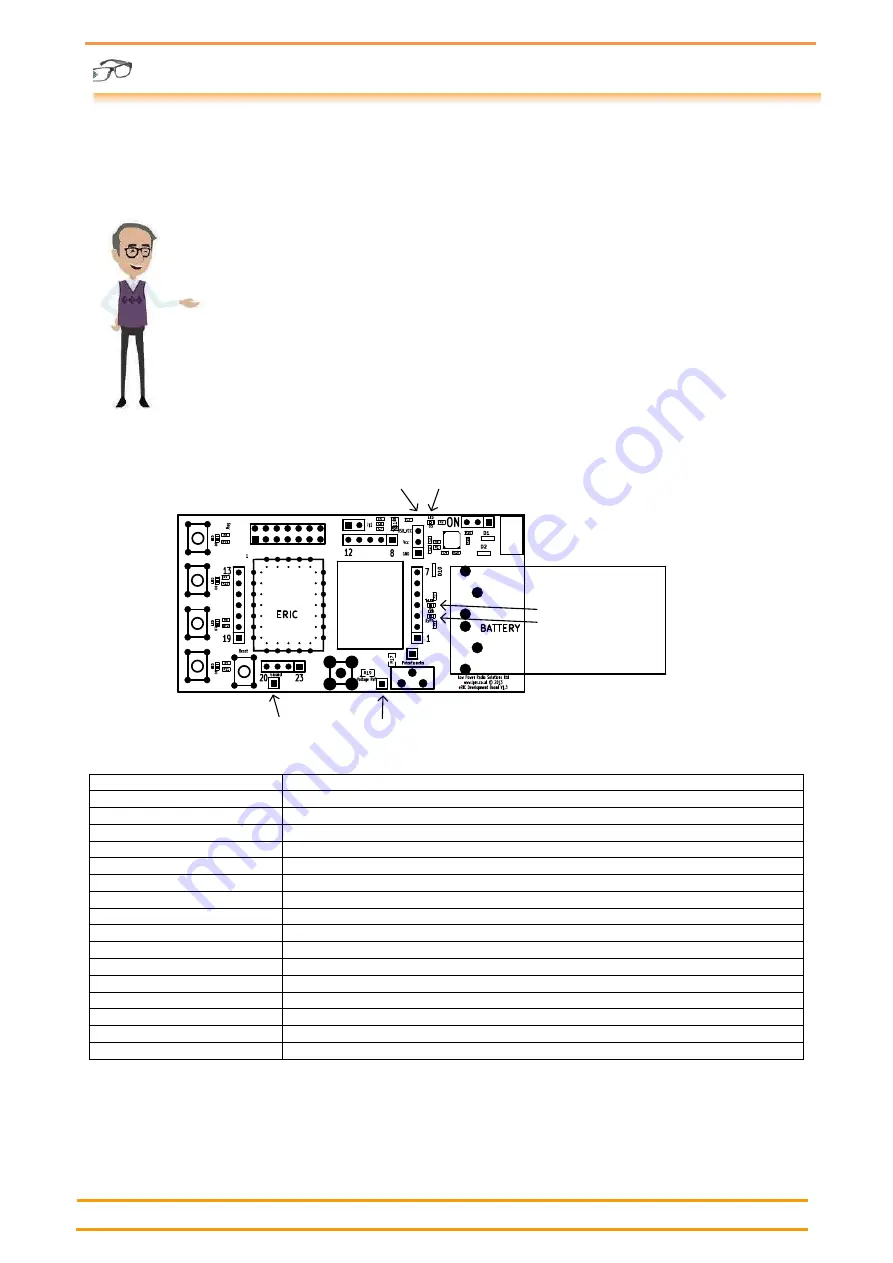
Development Board Description
N.B. Board supplied may differ slightly from illustration
JTAG Connector
JP1
SW1/LED1
Pin 16
SW2/LED2
Pin 17
SW3/LED3
Pin 18
SW4/LED4
Pin 19
Reset
RF In/Out
VRef
Gnd Pin
Potentiometer
9V PP3 Battery
Micro USB
Connector
On/Off Switch
Vcc Out
Tx LED - Red
Rx LED - Green
Pwr LED
Feature
Description
SW1/LED1 to SW4/LED4
Momentary push button switch and LED indicator connected to eRIC I/O pins
JTAG Connector
TI compatible JTAG programming connector
JP1
Bootloader enable jumper. Jumper in place to enable bootloader mode
Vcc Out
5V or 3V3 (20mA max) outputs and Gnd Ref for powering external circuitry
Pwr LED
Indicates that board is powered
On/Off Switch
Board power On/Off
Micro USB Connector
USB Serial Data and 5V USB power
Battery
9V PP3 battery for board power
Tx LED (Red)
Indicates serial USB data activity
Rx LED (Green)
Indicates eRIC receive data activity
Potentiometer
Provides variable voltage output on adjacent pin for testing A-D etc.
VRef
‘Top’ of potentiometer. Connect to Vcc Out pin 5V/3V3 or other voltage
RF In/Out
50R SMA Female RF connector for antenna or test equipment connection
Gnd Pin
0V Gnd reference for ‘scope or other test equipment.
Reset Switch
Momentary push button eRIC reset switch


