7
PCM_V1 07 .2017
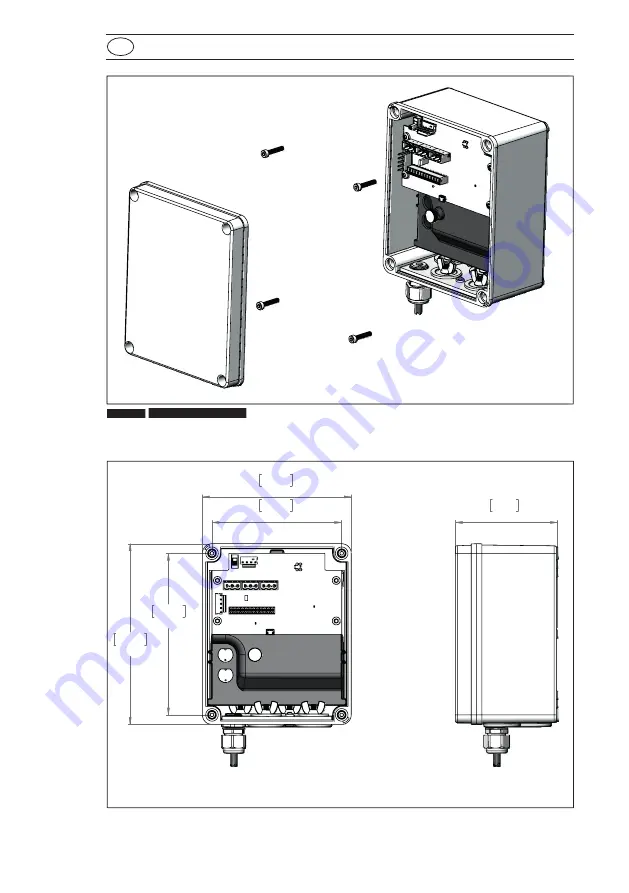
Figure 1:
Mounting screw locations
GB
Installation
Figure 2:
Mounting and product dimensions
122mm
4.80in
152mm
5.98in
170mm
6.69in
140mm
5.51in
96mm
3.78in
Page 1: ...www lovibond com Power Communications Module Junction Box Manual Lovibond Water Testing Tintometer Group ...
Page 2: ......
Page 3: ... A 21 8 0 Troubleshooting 22 To Preserve Protect and Improve the Quality of the Environment Disposal of Electrical Equipment in the European Union Because of the European Directive 2002 96 EC your electrical instrument must not be disposed of with normal household waste Tintometer GmbH will dispose of your electrical instrument in a professional and environmentally responsible manner This service ...
Page 4: ...the instructions laid out in this manual Preface Do not exceed temperatures or time spans in any case All warning labels must NOT be removed and should be replaced if they become damaged or faded Important Information The PCM can be mounted to a panel or to a wall Notes on power connection The PCM should be permanently connected to mains power See local building codes for permanently connecting eq...
Page 5: ...th from ELECTRICAL shock DANGER A risk of CHEMICAL injury WARNING A risk of severe burn HOT SURFACE WARNING A risk of severe injury PROTECTIVE EYE WEAR required ATTENTION radio wave emissions Guide to Symbols Labels attached to the instrument should be strictly observed to avoid personal injury or damage to the instrument Refer to this document Guide to Symbols for information regarding the nature...
Page 6: ...ransportation Store the packing material to return the unit for repair or other kinds of transport The table below shows the parts included in the packing Part List Mounting 1 Remove the front cover from the PCM 2 Align the PCM on the wall or panel and mark and drill 4 mounting holes 3 Install 4 M4 x 20 or similar mounting screws Part Description Quantity 1 PCM 1 2 Instruction Manual 1 ...
Page 7: ...PCM_V1 07 2017 Figure 1 Mounting screw locations GB Installation Figure 2 Mounting and product dimensions 122mm 4 80in 152mm 5 98in 170mm 6 69in 140mm 5 51in 96mm 3 78in Figure 1 Mounting screw locations ...
Page 8: ...voltage barrier GB Installation High Voltage Installation NOTICE A local disconnect mounted in a suitable and easily reached location must be included in the installation of this equipment The local disconnect must be marked as the disconnecting device for this equipment NOTICE This unit was tested with metallic conduit as per UL 61010 1 with a bending moment of 34Nm 300 lb in at a horizontal dist...
Page 9: ...9 PCM_V1 07 2017 Figure 3 Red thumb screw J3 and J9 locations Figure 4 Remove high voltage barrier GB Installation ...
Page 10: ...beled J2 J3 and J4 Note that Normally Open NO and Normally Closed NC contacts are provided See Figure 6 for wiring information 6 Reinstall the low voltage board connectors at position J3 and J9 and the red thumb screw GB Installation High Voltage Installation DANGER ELECTRIC SHOCK HAZARD The barrier must stay in place except when a qualified installation technician is connecting power or relay out...
Page 11: ...y Connections Figure 5 Power Connector Terminal Function Color North America Color EU 1 L1 Hot Black Brown 2 N Neutral White Blue 3 GND Protective Earth Green Green Yellow Terminal Label Function 1 NO Normally Open 2 COM Common 3 NC Normally Closed ...
Page 12: ...plate The two near the front are intended for low voltage use 2 Connect 0 20mA or 4 20mA devices to connectors labeled J5 and J6 Terminal Label Function 1 Analog 2 Analog 3 S Shield 3 If using the RS 485 MODBUS version connect the RS 485 network to connector J7 Terminal Label Function 1 RS 485 2 RS 485 3 S Shield ...
Page 13: ...13 PCM_V1 07 2017 GB Installation Figure 7 4 20 mA connections Figure 8 RS 485 connection ...
Page 14: ...he factory If the cable is removed during installation connect the positions as follows Terminal Color Function 1 BLACK 24VDC GND 2 RED 24VDC 3 WHITE RS232 TXD 4 GREEN RS232 RXD 5 YELLOW RS485A 6 GRAY RS485B 7 PINK 4 20 8 BLUE 4 20 9 ORANGE CANL 10 TAN CANH 11 BROWN FLOW 12 VIOLET PE Low Voltage Installation ...
Page 15: ...15 PCM_V1 07 2017 GB Installation Figure 9 12 pin connection ...
Page 16: ... on the network Analog Outputs The two isolated 0 20 4 20mA outputs are controlled by the sensor See the sensor manual for assigning zero and full scale to each analog output and trimming the analog outputs Power Indicator A green power indicator is provided at location LED1 This illuminates anytime there is power present on the low voltage board USB Power Indicator The USB power indicator illumin...
Page 17: ...17 PCM_V1 07 2017 Figure 10 Feature locations Low Voltage Board GB Operation 8 8 8 Figure 11 Feature locations High Voltage Board ...
Page 18: ...two 1 6A 250VAC fuses Should the fuses need changing disconnect the unit from AC power and open the cover with a suitable tool to access the fuses Figure 11 Fuse locations DANGER DISCONNECT POWER BEFORE SERVICING Always remove AC power from the PCM before performing maintenance on the device ...
Page 19: ... Maintenance Cleaning No special maintenance is necessary apart from periodic cleaning of the unit Disconnect the unit from AC power and use a dust free cloth with a non flammable non aggressive detergent to clean the unit ...
Page 20: ... Details Power supply 100 240V 50 60Hz Power 40W Output 24VDC for one instrument Analog Outputs 2 0 20 4 20mA isolated outputs 10VDC loop voltage Relay Outputs 3 100 240V 5A resistive maximum Size 6 7 x 5 5 x 3 7 Weight 3 8 lbs Construction materials Thermoplastic enclosure IP Rating IP66 Conduit holes 4 Operating Temperature 0 to 50C 32 to 122F Humidity 0 95 RH Non condensing Digital communicatio...
Page 21: ...onment This equipment generates uses and can radiate radio frequency energy and if not installed and used in accordance with the instruction manual may cause harmful interference to radio communications Operation of this equipment in a residential area is likely to cause harmful interference in which case the user will be required to correct the interference at his own expense Shielded Cables Conn...
Page 22: ...on with sensor Check cable at position J3 on low voltage board Relays on continuously Check connection with sensor No green power light Check fuses Check AC mains circuit breaker Check cable at J9 on low voltage board No USB connection Check USB power LED1 USB driver not found Download and install CP210x Win dows Drivers driver from Silicon Labs www silabs com ...
Page 23: ......
Page 24: ... info tintometer ch www tintometer ch Switzerland The Tintometer Ltd Lovibond House Sun Rise Way Amesbury Salisbury SP4 7GR Tel 44 0 1980 664800 Fax 44 0 1980 625412 sales tintometer com www lovibond com UK Tintometer Inc 6456 Parkland Drive Sarasota FL 34243 Tel 941 756 6410 Fax 941 727 9654 sales tintometer us www lovibond com USA Tintometer Brasilien Caixa Postal 271 CEP 13201 970 Jundiaí SP Te...