background image

Pan/Tilt/Zoom (PTZ) Cameras

17

STEP 2: Camera configuration

1. From the Live View display, right-click to open the Quick Menu, then click

Main Menu

.

2. Click

CAMERA

, then click the

IMAGE SETTINGS

tab.

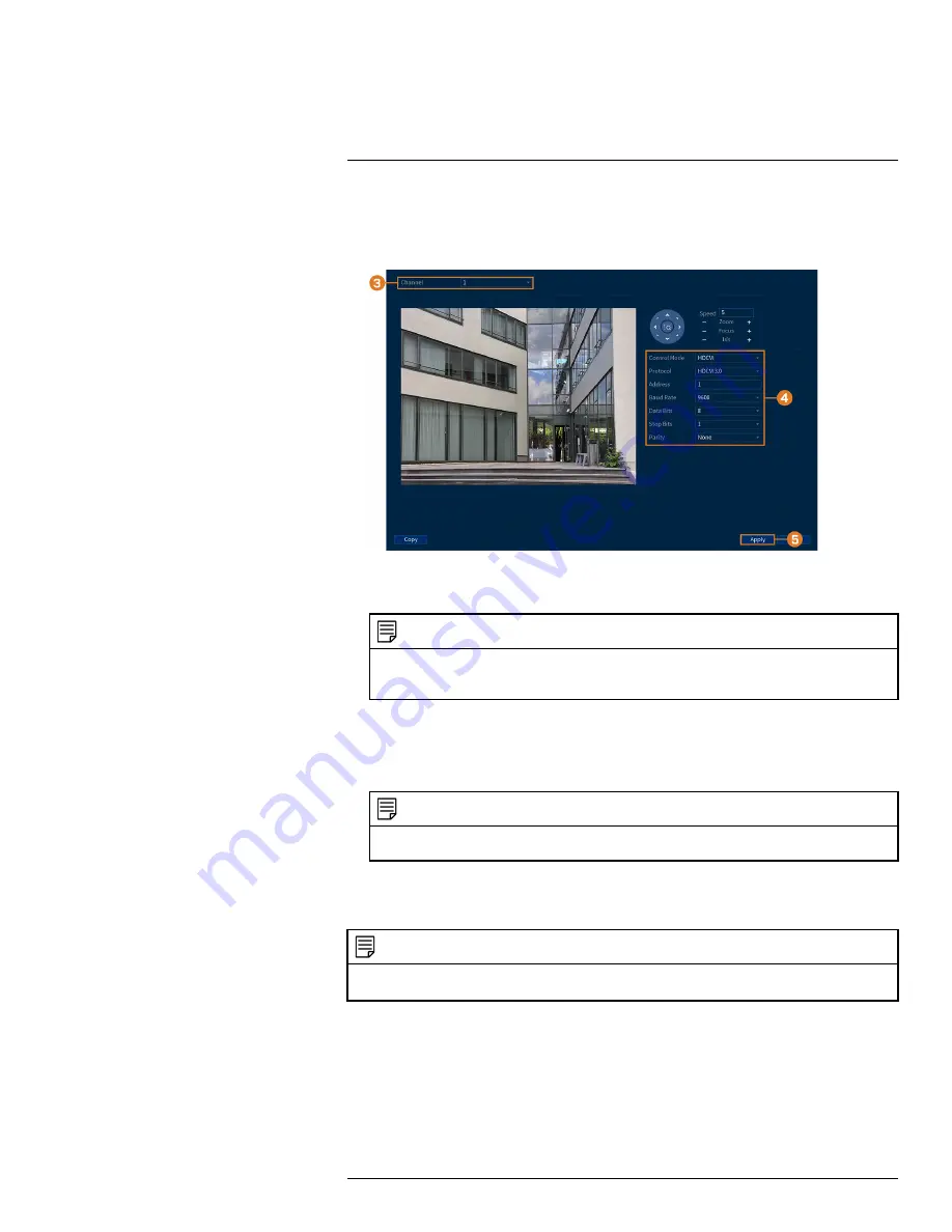
3. Select the channel you want to configure.
4. Configure the highlighted fields as needed.

NOTE

For Lorex HD PTZ cameras, there is no need for configuration — leave all fields at their default values. For
third-party PTZ cameras, select

Serial

next to

Control Mode

. For the correct settings to use in the remaining

fields, please reference your camera documentation.

5. Click

Apply

.

6.

(OPTIONAL)

Click

Copy

to apply the settings for the current channel to one or more other

channels (see 15.12

Copying Settings to Another Channel

, page 89 for full instructions on us-

ing the copy function).

NOTE

If you copy settings over to connect multiple PTZ cameras, please note that each camera requires a unique ad-
dress. You cannot use the same address for 2 different cameras.

17.2

Basic PTZ Controls

Controlling PTZ cameras.

NOTE

Ensure you have completed initial setup of your PTZ camera in order to control the camera using the recorder. See
17.1

Connecting PTZ Cameras to the Recorder

for more details.

To access the PTZ controls:

Open the Live View screen for your PTZ camera in single-channel view (fullscreen). Right-
click to open the Quick Menu, then click

Pan/Tilt/Zoom

.

Right-click again to close PTZ controls.

To use the PTZ controls:

#LX400111; r. 5.0/56647/56647; en-US

92

Summary of Contents for D861 Series

Page 1: ...User Manual D861 Series...

Page 2: ......

Page 3: ...User Manual D861 Series LX400111 r 5 0 56647 56647 en US iii...

Page 4: ...G TO QUALIFIED SERVICE PERSONNEL The lightning flash with arrowhead symbol within an equilateral triangle is intended to alert the user to the presence of uninsulated dangerous voltage within the prod...

Page 5: ...stalling Cameras 12 5 5 Connecting Camera Extension Cables 13 6 Using the Mouse 14 7 Using the On Screen Display 15 7 1 Navigation Bar 15 7 2 Quick Menu 15 7 3 Camera Toolbar 16 7 4 On Screen Keypads...

Page 6: ...ps 50 14 2 2 Modifying Groups 51 14 2 3 Deleting Groups 52 15 Using the Main Menu 53 15 1 Main Menu s Navigation Bar 53 15 2 Playback 54 15 3 Events 54 15 3 1 Video Loss 54 15 3 2 System Warnings 55 1...

Page 7: ...5 15 11 6 Online User 86 15 11 7 Network Load 86 15 11 8 Test 87 15 11 9 Restoring Default Settings 87 15 11 10Upgrading Firmware Manually 87 15 11 11Automatic Firmware Upgrades 88 15 11 12Import Syst...

Page 8: ...9 22 3 Display 109 22 4 Recording 109 22 5 Playback 109 22 6 Storage 109 22 7 Special Features 110 22 8 Smart Home 110 22 9 Connectivity 110 22 10 Additional Specifications 110 23 Notices 111 23 1 FCC...

Page 9: ...internal battery that will keep the product running in the event of a power outage CAUTION Maintain electrical safety Power line operated equipment or accessories connected to this product should bea...

Page 10: ...le oper ation of the product and to protect it from overheating These openings must not be blocked or covered The openings should never be blocked by placing the product on a bed sofa rug or other sim...

Page 11: ...sed have the same safety characteristics as the original parts Use of re placements specified by the product manufacturer can prevent fire electric shock or other hazards 4 Safety Check Upon completio...

Page 12: ...ter Ethernet Cable USB Mouse HDMI Cable NOTE Hard drive size number of channels and camera configuration may vary by model Please refer to your package for specific details Check your package to confi...

Page 13: ...e not included for data backup or manual firmware updates 3 2 Back Panel 1 Video Inputs Connect Lorex HD or standard analog cameras to the system For a full list of compatible cameras visit lorex com...

Page 14: ...he system or a USB flash drive not included for data backup or manual firmware updates 7 DC 12V Connect the included power adapter 8 ON OFF Switch Turns the DVR on off 9 VGA Connect a VGA monitor not...

Page 15: ...naming and organizing your cameras so it is also recommended to leave cameras connected until the wizard asks you to install cameras in their permanent mounting location NOTE Before selecting a perman...

Page 16: ...Connect power Use the included power adapter to connect the recorder to a nearby outlet Turn the recorder on us ing the power switch on the back panel 4 6 STEP 6 Lorex Setup Wizard When you first powe...

Page 17: ...irmware upgrades If a firmware upgrade is available 1 After startup a notification will appear asking you to upgrade the firmware Click OK to upgrade 2 Enter the system user name default admin and you...

Page 18: ...lay right click to open the Quick Menu then click Info OR Press the front panel button on the recorder NOTE Do not press and hold the button The front panel button doubles as a panic button that activ...

Page 19: ...t it is not exposed or easily cut Mount the camera in an area that is visible but out of reach Avoid pointing the camera at a glass window to see outside This may result in a bright white ring in the...

Page 20: ...head on to capture a person s entire face looking straight ahead Obscured and or partially or fully covered faces i e a person s head tilted down to look at their phone will not be accurately detecte...

Page 21: ...ble must be a single stretch of cable between the recorder and camera You cannot connect multiple extension cables to each other For all extension cable options including maxi mum extension cable leng...

Page 22: ...mode click an individual channel to view it in full screen Click again to return to the split screen display mode While navigating menus click to open a menu option 2 Right button During live view ri...

Page 23: ...le through connected channels every few seconds 5 Playback Opens the Playback Menu This allows you to search for video recordings saved on the recorder s hard drive For details on using the Playback m...

Page 24: ...tions from Live Mode 1 Continuous for a full view of all channels live streaming or set to 2 AI to include Face Detection events on the right of the screen 11 Image Settings Configure camera image set...

Page 25: ...Using the mouse click on a field where alphanumeric characters are entered such as the user name and password fields The Full Keypad opens Click Shift to switch between uppercase and lowercase charact...

Page 26: ...nd corner of the camera image when motion is detected 8 2 Configuring Recording Quality The system uses two video recording streams a Main Stream and a Sub Stream The Main Stream records high quality...

Page 27: ...n Frames Per Second FPS that each stream will record at A higher frame rate provides a smoother picture but will require more storage and bandwidth Bit Rate Type Select CBR Constant Bit Rate or VBR Va...

Page 28: ...hedules at once To make fine adjustments to a schedule click This will allow you to set exact start and end times for a schedule To disable all recording of the selected type on the selected day click...

Page 29: ...p The system will not record the Sub Stream for this channel This option is not recommended 4 Under Snapshot select Enable to enable snapshot recording on each channel Or select Dis able to disable sn...

Page 30: ...Recording 8 4 Click Apply LX400111 r 5 0 56647 56647 en US 22...

Page 31: ...lect the day to playback 3 Check the channels you want to play back Click the icons to the right of each channel name to choose the video quality for Main Stream for Sub Stream 4 Click inside the vide...

Page 32: ...se lected date File List Shows all available recordings for the selected date and channel s in list format Fullscreen Shows video in fullscreen Right click to return to split screen viewing 5 Zoom Pl...

Page 33: ...an external speaker to the recorder in order to hear audio Digital Zoom Click to enable digital zoom Click and drag over the camera image to zoom in on the selected area Right click to return to the f...

Page 34: ...e day to playback 3 Check a single channel you want to play back Click the icon to the right of the channel name to choose the video quality for Main Stream for Sub Stream 4 Click inside the video bar...

Page 35: ...b Stream 5 Click inside the video bar to select the playback time The system will begin playing back vid eo from the selected time 6 Click to mark the beginning of the video clip then click again to m...

Page 36: ...n the Quick Menu then click Main Menu 2 Click BACKUP 3 Click Format next to the Device Name 4 Select a format mode FAT32 Recommended offers the greatest compatibility with other devices NTFS Advanced...

Page 37: ...software 4 Click Add A list of files that match your search criteria appears 5 Check files you would like to backup 6 Click Backup NOTE HD video files saved on the system may take up a large amount o...

Page 38: ...ols page 31 10 4 2 Viewing Backed Up Files on Mac 1 Download and install the Lorex Player for Mac from the recorder s product page at lorex com 2 Double click the downloaded file in Safari to extract...

Page 39: ...4 3 Lorex Player Controls 1 File List Double click to open a file 2 Viewing Mode Select between single channel viewing and various split screen options 3 Hide Show File List 4 Playback Controls Playb...

Page 40: ...video file to a different format 9 Digital Zoom Click then click and drag over a camera image to zoom in Right click to re turn to the full image 10 Drag Click then click and drag to move around a cam...

Page 41: ...each channel and select channels you want to enable smart Person and Vehicle detection on To configure motion detection 1 From the Live View display right click to open the Quick Menu then click Main...

Page 42: ...eal zone selection You can set up to 3 different zones with different sensitivity and threshold values Right click when finished 6 Click Setup next to Schedule to choose which days and times of the we...

Page 43: ...ered tiles next to this option to in clude the corresponding channels in the sequence Snapshot Select the numbered tiles next to this option to save a snapshot of the corre sponding channels Buzzer Ch...

Page 44: ...display right click to open the Quick Menu then click Main Menu 2 Click EVENTS Click the Smart Search tab on the side panel then Smart Motion on the top panel 3 Select the channel to search for events...

Page 45: ...cannot enable Face Detection and Person and or Vehicle detection on any channel at the same time In order for Face Detection to be enabled all Smart Motion Detection Person and Vehicle needs to be dis...

Page 46: ...detection Click or click and drag along the each of the blue timelines to quickly add or remove time from each day s schedule in 15 minute segments Click beside 2 or more days to link schedules This...

Page 47: ...or go to a preset location Sequence Sequence mode will begin Select the numbered tiles next to this option to in clude the corresponding channels in the sequence Snapshot Select the numbered tiles nex...

Page 48: ...lick and drag along the each of the blue timelines to quickly add or remove time from each day s schedule in 15 minute segments Click beside 2 or more days to link schedules This allows you to quickly...

Page 49: ...he highest Click OK 9 Click the icon under Parameters to set the alarms for face recognition 10 Click Apply to save all changes 12 3 Create a Face Database To build your face database you can create a...

Page 50: ...in the face database list 12 3 1 Add a Face by USB to the Database To add a face to the face database 1 From the Live View display right click to open the Quick Menu then click Main Menu 2 Click EVENT...

Page 51: ...ted in batches which is useful when adding a large number of faces at one time 12 3 3 Add Captured Faces You can add images to build the face database by using images that have been captured in AI mod...

Page 52: ...dd to Face Database for the register window to appear 4 Check the box next to the database that you want to add the face to 5 Add additional details for the face entry including name 6 Click OK to sav...

Page 53: ...nd sirens manually using the recorder or the Lorex Home app see 13 2 Manually Activate Deterrence Features page 47 For a complete list of compatible deterrence cameras navigate to your recorder series...

Page 54: ...Light for a solid white light or Strobe for a flashing light If you select Strobe set how quickly the light will flash under Strobe Frequency 6 Click Setup next to Area to set an active area for autom...

Page 55: ...tures The system has multiple options for activating deterrence features To activate deterrence features on a single camera Hover the mouse pointer near the top of the camera image in Live View to rev...

Page 56: ...access to system settings and camera feeds 14 1 1 Changing Passwords You can change the system password of the administrator and user accounts To change an account password 1 From the Live View displ...

Page 57: ...sign what menus they have access to For example you may want your friend to monitor your system while you are away while not giving full access to your system To add a user 1 From the Live View displa...

Page 58: ...ve access to the menus you assigned 14 1 3 Modifying Users Modify account details such as account username or permissions To modify a user 1 From the Live View display right click to open the Quick Me...

Page 59: ...account to have Under the Sys tem tab select the menus the user account may access Under the Playback tab select which channels the user account may access recorded video from Under the Covert tab sel...

Page 60: ...ick OK 14 2 3 Deleting Groups Remove a group To delete a group 1 From the Live View display right click to open the Quick Menu then click Main Menu 2 Click ACCOUNT then click the GROUP tab 3 Click nex...

Page 61: ...k page 23 2 Events Set preferences for events such as video loss motion detection Person Vehicle detec tion Face Detection Face Recognition and system warnings The Events menu is also used to set pref...

Page 62: ...cameras 15 3 1 Video Loss Configure video loss settings and how the system reacts to a video loss event Video loss means that video from one or more cameras was interrupted or disabled It could be ca...

Page 63: ...TZ cameras to start a tour pattern or go to a preset location Sequence Sequence mode will begin Select the numbered tiles next to this option to in clude the corresponding channels in the sequence Sna...

Page 64: ...w Message Error message will appear on the recorder s display Buzzer The recorder will sound an audible alarm Send Email Send an email notification with details on the event requires email configura t...

Page 65: ...rch all channels for events including motion detection and video loss To search for events 1 From the Live View display right click to open the Quick Menu then click Main Menu 2 Click Events then clic...

Page 66: ...order to an output resolution sup ported by the new monitor before switching To change the output resolution 1 From the Live View display right click to open the Quick Menu then click Main Menu 2 Clic...

Page 67: ...age 96 for details To set preferences for listen in audio 1 From the Live View display right click to open the Quick Menu then click Main Menu 2 Click DISPLAY then click the Display tab 3 Check Live A...

Page 68: ...he current menu will update instantly to show how other menus will be affected 4 Click Apply 15 5 4 General Display Settings Configure miscellaneous display settings To configure general display setti...

Page 69: ...s 6 Check the AI Rule to detect faces in the frame 7 Click Apply NOTE You can also adjust where the time and channel name overlays are positioned on screen See 15 6 3 Changing On Screen Overlay page 6...

Page 70: ...reen when Sequence mode is triggered by mo tion detection must be configured separately see page for details 6 Select a viewing mode to configure It is recommended to start with View 1 and make your w...

Page 71: ...To configure snapshot recording 1 From the Live View display right click to open the Quick Menu then click Main Menu 2 Click CAMERA Click the Recording tab on the side panel then Snapshot on the top p...

Page 72: ...y on the top panel 3 Select the channel you want to configure 4 Click and drag the blue boxes on the camera image to adjust the location of the date time and channel name 5 Use the checkboxes to enabl...

Page 73: ...5 Active privacy masks are shown on the camera image Click and drag to move a privacy mask or click and drag the edge of a privacy mask to resize it 6 Click Apply 15 6 5 Connecting Multi Format Camera...

Page 74: ...firmware This is typically only necessary if directed to do so by Lorex technical support Prerequisite Connect a USB flash drive not inlcuded to the recorder with the bin camera firmware file s prelo...

Page 75: ...igure the following IP Address Enter the IP address you would like to assign to the system Make sure that no other device on your network is using the same IP address Subnet Mask Enter the subnet mask...

Page 76: ...em to send out email alerts for motion detection or other events NOTE To send out motion detection alerts you must enable the Send Email option for motion detection on each camera you would to receive...

Page 77: ...Using the Main Menu 15 2 Click NETWORK then click the Email tab 3 Click to enable email alerts LX400111 r 5 0 56647 56647 en US 69...

Page 78: ...TP server Username Enter the SMTP user name Password Enter the SMTP password Email Schedule Click to setup a weekly schedule for email alerts Receiver Select up to 3 email addresses that will receive...

Page 79: ...the Quick Menu then click Main Menu 2 Click NETWORK then click the P2P tab 3 Click to enable disable P2P connectivity 4 Click Apply 15 8 System Configure general system settings such as date time time...

Page 80: ...fore the system will logout the current user Navigation Bar Check to enable the Navigation Bar that comes up when you left click in live view Mouse Pointer Speed Use the slider to adjust the mouse spe...

Page 81: ...e g 2nd Sunday of March or select Date to set the start and end time to a specific date Start Time End Time Set start and end times for DST Format will change depending on your selection for either We...

Page 82: ...ick SYSTEM click the General tab then Holiday on the top panel 3 Click Add 4 Configure the following Name Enter a name for this holiday Effective Mode Select Once for the holiday to occur only this ye...

Page 83: ...the Quick Menu then click Main Menu 2 Click SYSTEM click the Security tab then clickFirewall on the top panel 3 Click to enable disable the selected filter type 4 Under Mode select which type of filt...

Page 84: ...Apply 15 8 5 Configuring IP Filter Sync Time Configure permissions for external IP addresses that are permitted to sync the recorder s time To configure the IP filter 1 From the Live View display righ...

Page 85: ...ation to a USB flash drive not in cluded This is useful if you want to backup your current settings NOTE This function only saves settings created in system menus It does not save or backup any video...

Page 86: ...click Main Menu 2 Click STORAGE then click the Basic tab 3 Ensure HDD Full is set to Overwrite to overwrite the oldest recordings when the hard drive is full NOTE Selecting Stop for the system to stop...

Page 87: ...you would like to configure or select All 4 Set the duration for pre recording in seconds 5 Click Apply 6 OPTIONAL Click Copy to apply the settings for the current channel to one or more other channel...

Page 88: ...ine adjustments to a schedule click This will allow you to set exact start and end times for a schedule To disable all recording of the selected type on the selected day click 5 Click Apply 6 OPTIONAL...

Page 89: ...ive but it will not record to it To configure hard drive types 1 From the Live View display right click to open the Quick Menu then click Main Menu 2 Click STORAGE then click the HDD Manager tab 3 Und...

Page 90: ...the total storage needed to record for a specific number of days 4 For Recording Days mode click Select to choose your hard drive from a list to output the to tal number of days your hard drive can st...

Page 91: ...a day of the week to configure FTP recording settings for or select All to apply to all days of the week Period 1 Period 2 Select up to 2 periods of time where the system will save recordings to the...

Page 92: ...nfo tab then Version on the top panel 15 11 2 Disk Information related to the hard drives installed in the system including capacity status and type To access the disk menu 1 From the Live View displa...

Page 93: ...p panel 15 11 4 Log The Log menu allows you to search for system logs To search for system logs 1 From the Live View display right click to open the Quick Menu then click Main Menu 2 Click INFORMATION...

Page 94: ...ess Video Loss Shows disconnected channels Motion Shows channels with active motion alarms 15 11 6 Online User The Online User menu shows a list of users connected to the system using computers or mob...

Page 95: ...ick to open the Quick Menu then click Main Menu 2 Click INFORMATION click the Update Reset tab then click Default on the top panel 3 Click Default to reset all parameters to default settings except fo...

Page 96: ...des if it is connected to the Internet To configure automatic firmware upgrade 1 From the Live View display right click to open the Quick Menu then click Main Menu 2 Click INFORMATION click the Update...

Page 97: ...the configuration files you would like to restore Configuration file fold ers are labeled Config and then the time and date the configuration was saved e g Config_ 20200611133747 5 Click Import to sa...

Page 98: ...display right click to open the Quick Menu then click Main Menu 2 Click CAMERA then click the VOICE ASSISTANCE tab 3 Click to enable disable voice assistance 4 Check channels you would like to enable...

Page 99: ...can accept PTZ commands directly through the video cable If you are using a standard definition PTZ camera you will need to run the camera s RS485 ca bling to the recorder in order to send PTZ command...

Page 100: ...rent channel to one or more other channels see 15 12 Copying Settings to Another Channel page 89 for full instructions on us ing the copy function NOTE If you copy settings over to connect multiple PT...

Page 101: ...cus on objects closer to the camera Iris Controls the amount of light coming through the lens Click to allow more light or for less 5 Advanced Expand to show advanced options For a full overview see 1...

Page 102: ...tings Not supported 17 4 Presets Presets will save a camera position for quick retrieval To add preset locations 1 From the Live View display of your PTZ camera right click to open the Quick Menu then...

Page 103: ...a in any pattern you wish When finished click End To run a pattern Under No select the number of the pattern you want to go to then click 17 7 AutoScan An autoscan automatically cycles between a left...

Page 104: ...the system requires audio capable camera or self power microphone To enable audio recording using a Lorex HD audio camera 1 From the Live View display right click to open the Quick Menu then click Mai...

Page 105: ...ng on the top panel 3 Select Channel 1 NOTE Use of an external microphone allows you to record audio on Channel 1 of the system It cannot be moved to a different channel 4 Click Audio Setting then con...

Page 106: ...fore removing installing a hard drive To remove the hard drive 1 Power off the system and unplug all cabling from the system 2 Turn the recorder over Remove the bottom panel screws 6 3 Turn the record...

Page 107: ...l being mindful of the sharp edges of the bottom panel Remove the hard drive screws 4 from the bottom panel Hold onto the hard drive so it remains in place when all screws have been removed 6 If you a...

Page 108: ...before removing installing a hard drive To install a new hard drive 1 Insert the 2 hard drive screws closest to the SATA and power ports on the hard drive and tight en them half way 2 Power off the s...

Page 109: ...ION The wiring to the front panel button and USB port runs along the top panel of the recorder When separating the top panel rest it carefully beside the bottom panel as shown below 5 Line the 2 half...

Page 110: ...arp edges of the bottom panel Slide the 2 pre inserted screws into the locked position then tighten the screws Insert and tighten the 2 remaining hard drive screws 7 Connect the power and SATA cables...

Page 111: ...mobile devices see page 20 1 STEP 1 Port Forwarding If you are using DDNS you must port forward the HTTP and Client Ports default 80 and 35000 on your router to your recorder s IP address before you c...

Page 112: ...anufacturer s warranty on your recorder To activate your product warranty 1 From your Lorex account click the WARRANTIES tab 2 Click Activate Warranty 3 Enter your product information attaching bill o...

Page 113: ...Add Device Once submitted your DDNS account information will be summarized under My DDNS Devi ces Make a note of your DDNS URL Username and Password as they will be needed to complete DDNS setup 20 5...

Page 114: ...in the DDNS confirmation email 5 Click Apply You will now be able to access your system remotely using DDNS Enter the full domain name into a web browser e g http www tomsmithsecurity lorexddns net an...

Page 115: ...hard drive in the system Open the housing and install com patible hard drive Make sure to for mat the drive after installing For details see 15 9 5 Formatting the Hard Drive page 80 Hard drive is ful...

Page 116: ...Audio Devices page 96 for details on using audio enabled devices The system beeps during motion detection Motion detection is enabled and the buzzer is activated See page for full instructions on con...

Page 117: ...cording Resolution 4K 5MP 4MP 3MP 1080p 720p Recording Frame Rate 4K 7fps NTSC 5MP 12fps 4MP 3MP 15fps 1080p 30fps 720p 30fps Recording Schedule Per Channel by Continuous Motion Smart Motion Person Ve...

Page 118: ...ectivity Mobile Viewing Android iOS Compatible App Lorex Home PC MAC Remote Viewing Yes Lorex Cloud Email Notification Text and Snapshot Network Interface 10 100 Base TX RJ45 DDNS Yes Optional USB Int...

Page 119: ...interference to radio communications 23 2 CE This product and the supplied accessories are marked with CE and comply with the applicable harmonized European standards listed under Low Voltage Directiv...

Page 120: ...LX400111 r 5 0 56647 56647 en US 112...

Page 121: ......

Page 122: ...er registered trademarks or trademarks of Lorex Corporation and or its subsidiaries All other trademarks trade names or company names referenced herein are used for identification only and are the pro...

Reviews: