background image

4

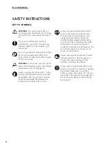
KEY TO SYMBOLS

WARNING!

 This symbol means that you 

should pay particular attention and is always 
followed by information about the relevant 
risk.

This symbol is followed by important 
information or instructions. Pay particular 
attention when this symbol appears in the 
manual text.

For your own safety and the safety of others, 
do not use the equipment without first 
having read and understood all the contents 
of this user manual.

WARNING!

 Cutting tools: Incorrect use can 

lead to life-threatening injuries. Band blades 
are extremely sharp and dangerous.

Always use protective gloves (class 1) when 
working with the band sawmill or handling 
band blades. Risk of sustaining cuts when 
handling band blades. Band blades and 
engine parts can be hot after sawing.


Always use approved hearing protection 
when working with the machine. Even 
short exposure to high frequency noise 
can damage your hearing. Always use 
closefitting safety goggles when working 
with the machine or handling band blades. 
Under certain circumstances the use of 
respiration protection may be necessary. This 
would mainly apply if you are sawing dry 
wood or sawing indoors.

Always wear approved protective footwear 
with saw protection, steel toe-caps and 
nonslip soles when working with the 
machine or handling band blades.

Always wear full-length protective trousers 
when working with the machine or handling 
band blades. Never wear loose-fitting 
clothing, scarves, neck chains, etc., that can 
get caught in the machine during operation. 
Secure loose hair before working with the 
band sawmill.

SAFETY INSTRUCTIONS

Summary of Contents for SMART SET

Page 1: ...USER MANUAL Ref no 0458 395 5352 SMART SET AUTOMATION EN UP DOWN ...

Page 2: ...ult in serious or fatal injuries to the operator or others We are very pleased that you have demonstrated your confidence in us by purchasing this product and we will do our utmost to meet your expectations Logosol has been manufacturing sawmills since 1989 In that time we have supplied approximately 50 000 machines to satisfied customers the world over We care about your safety as well as we want...

Page 3: ...Safety instructions 4 Start and stop 6 Functions 7 TABLE OF CONTENTS ...

Page 4: ...ling band blades Band blades and engine parts can be hot after sawing Always use approved hearing protection when working with the machine Even short exposure to high frequency noise can damage your hearing Always use closefitting safety goggles when working with the machine or handling band blades Under certain circumstances the use of respiration protection may be necessary This would mainly app...

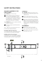
Page 5: ...l panel and the engine Enabling switch on the control panel The eneabling switch is a lock between the operator and the control panel To be able to run the software the enabling switch button has to be pressed down OPERATOR WARNING Whenever the machine is used approved personal protective equipment must always be used Persons under the age of 18 may not work with the band sawmill or handle band bl...

Page 6: ...e as the enabling switch button is being pressed down 5 This brings the engine up to its operating speed and the band blade starts rotating 6 If the choke is in its closed position gradually move the control lever towards its open position as the enging gets hotter STOP You stop the band blade by releasing the control lever or the enabling switch button Then the band blade will stop and the engine...

Page 7: ...abling switch button is a safety function It is superior to the control unit and has to be kept pressed down if the machine is to be activated The control unit of the Logosol Smart Set has a display a set of programs setting keys an enabling switch button and a control lever To use a function you select the desired one on the control panel Then to be able to execute the command the enabling switch...

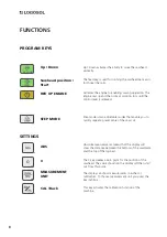
Page 8: ...n The engine revs up and then runs at working rpm until the control lever is released Up Down activates the ability to move the sawhead vertically The 0 key creates a zero point for the position of the sawhead The value shown on the display will then start out from this point The display can show measurements in inches or millimetres To choose measurement unit you press the key inch mm This key ac...

Page 9: ...awblade you can use the Cal key to put the machine in the calibration mode The Cal key is pressed down to start the calibration Then you move the sawblade with the control lever until it comes to the calibration value 100 mm from the log bed Be careful when measuring the position of the saw blade The precision when positioning the saw blade will directly reflect the accuracy of the dimensions of t...

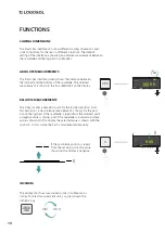
Page 10: ...e functions of the machine and is to be regarded as a lock between the keypad and the control lever To execute the selected command the enabling switch button has to be kept pressed down ENABLING SWITCH BUTTON UP DOWN The calibration key has two functions it also works as a command for cancelling a selected operation Pressing this button returns the machine to standby mode CANCEL COMMAND ...

Page 11: ...dby mode Keep the sawing dimension key pressed down and then enter the desired value using the control lever The value will be shown on the display next to the key to which the relevant command is connected The Step mode is activated by pressing one of the preset step keys The value will then be shown on the display To activate the command you push the control lever forward Now the sawhead is lowe...

Page 12: ... the steps that are performed by the Smart Set during sawing UP DOWN FUNCTIONS START POSITION To make a cut begin by setting the sawblade to the desired height Activate the feed and start the engine to enable sawing Feed the blade through the log using the control lever Activate Up Down to be able to raise the sawhead before bringing it back Activate the feed and bring the sawhead back to the star...

Page 13: ...rt the blade you have to be in the Feed mode and then press down the Start key Stop the engine by releasing the control lever to its 0 position REVVING UP THE ENGINE To be able to run the different functions in Smart Set you follow the steps as shown in the illustration below Select the desired function on the keypad Keep the enabling switch button pressed down Carry out the selected operation wit...

Page 14: ...tate for the user in different situations The default setting of the interface is showing an absolute measurement between the sawblade and the log bed in millimetres 1 2 3 4 A B C ABS 10 00 100 00 10 00 TOE BOARD MM REL ABS ABSOLUTE MEASUREMENTS RELATIVE MEASUREMENTS 1 2 3 4 A B C 10 00 0 00 10 00 TOE BOARD MM 0 0 The 0 key creates a new zero point for the log bed position From this zero point a n...

Page 15: ...15 ...

Page 16: ...Fiskaregatan 2 871 33 Härnösand SWEDEN 46 611 182 85 info logosol com www logosol com ...

Reviews: