


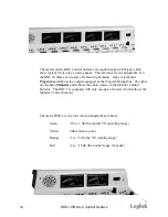


The fuse holder is adjacent to the power connector and contains a ½ amp fuse for
both ROC 5 and ROC 10 control surfaces.
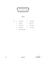
The second cable is the data cable which connects to the Audio Engine. This
cable has a male DB-9 connector on each end. On the control surface, this
connector is attached adjacent to the power connector. The wiring list for this
cable is shown in the Appendix. Maximum length of the cable is 300 meters or
1000 feet. These cables can be ordered through Logitek in the length you need.
Recommended wiring for this connection is Category 5 computer cable.
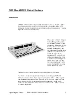
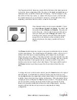
The ROC Console control surface consists of two pieces, a top and a tray. To
access the tray for mounting, remove the top by unscrewing the three screws
along the back edge of the top panel. Pull up on this edge and slide the panel
backwards as it comes loose. Two tabs on the front of the tray will disengage and
the top panel can then be removed. Reinstall the top by reversing this process.
8
ROC-10/ROC-5 Control Surface
Summary of Contents for ROC 10
Page 1: ...ROC 10 and ROC 5 Digital Audio Consoles...
Page 4: ...This page is intentionally blank iv ROC 10 ROC 5 Control Surface...
Page 17: ...This page is intentionally blank Logitek Digital Consoles ROC 10 ROC 5 Control Surface 17...
Page 18: ...This page is intentionally blank 18 ROC 10 ROC 5 Control Surface...
Page 26: ...26 Appendix...
Page 27: ...Logitek Digital Consoles Appendix 27 ROC 10 Installation Cutout...