INSTALLATION GUIDE
LS6000 Logic Net eStation
www.logiccontrols.com
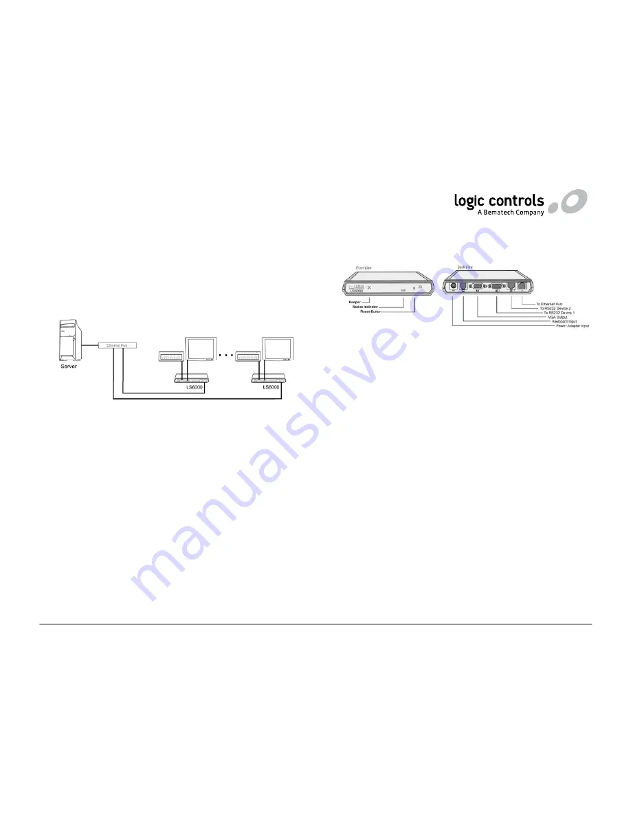
The LS6000 video I/O station is the Ethernet version of Logic Net, the
industry’s leading kitchen video display system solution. A typical system
consists of a host server (PC or POS terminal) where the application software
is installed and a number of LS6000 units. Each LS6000 eStation can be
connected to a VGA monitor, a keyboard, and 2 serial interface devices. The
LS6000 units communicate with the host server via TCP sockets on Ethernet
connections.
HARDWARE INSTALLATION
Component Placement
The following is recommended when you plan the LS6000 system setup:
•
Place the LS6000 so that you can use the mounting brackets located
at the bottom of the unit.
•
Place the LS6000 so that the RESET button is accessible.
•
Place the LS6000 so that the beeps from the speakers can be heard.
•
Place the LS6000 so that the LED indicator on the front panel can be
seen.
•
Place the LS6000 above grill/counter level, out of the way of possible
spills.
Mounting Instructions
Mounting brackets are provided to facilitate mounting the LS6000 to a wall,
ceiling, or display monitor mounting arm. The installer should insure that the
wall anchors used with the mounting brackets have the capacity to support 4.3
kg (9.5 lb.). This weight is determined by adding a safety margin weight to the
weight of the unit. Wall anchors with specified weight capacity are available
commercially.
Connections
Make sure that all systems are powered off before making or removing any
connections to the LS6000 unit. Follow the steps below in connecting the
devices:
1. Connect the VGA cable of the display monitor to the LS6000.
2. Connect the RS232 cable of serial devices to the LS6000.
3. Connect the keyboard device to the LS6000.
4. Connect the Ethernet cable from Ethernet hub or switch to the
LS6000.
5. Connect power to all peripheral devices and turn on power.
6. Connect power adapter to the LS6000 and power cord to the power
adapter.
7. Plug the power cord into AC power outlet.
8. If necessary, reset the LS6000 by pressing the reset button.
LS6000 SETUP AND SELF-DIAGNOSTIC TESTS
Each time the LS6000 is powered on, it runs a ROM-based setup and
diagnostic program that is used to set system parameters and provide
problem determination information. You can run the program by pressing the
system RESET button. As soon as the system information screen appears,
quickly press [Delete] or [Down Arrow] key on the keyboard to enter Setup
screen.
There are 5 setup menus: MAIN, ETHERNET, SERIAL, DIAGNOSTIC and
EXIT. The menu being displayed is highlighted on the menu bar across the
top of screen. Use left and right arrows to select the menu and use up and
down arrows to select menu item. Menu items that can be changed are
shown in yellow color and highlighted in reverse video when selected. Use
the -/+ keys or 0/1 keys to change the value. For certain items such as IP
address, the numeric keys are used to enter the values.


