background image


9

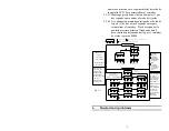
número se muestra en la esquina inferior derecha de 
la pantalla LCD.  Para reinicializar el contador; 

5.2.5.1


Mantenga presionado el botón de ajuste (3) por 
dos segundos para entrar al modo de Ajustes.   

5.2.5.2


A continuación mantenga presionado el botón de 
Ajuste (3) de tres a cinco segundos más para 
reinicializar el contador.  Tras dos segundos la 
pantalla mostrará primero “Guadando datos” 
pero continúe presionando hasta que el contador 
de ciclos regrese a 00000 . 


Fig. 5.1


Resolución de problemas 


Setup

TIMED MODE

P1

2.250

00004

SETUP MODE

P1

00004

SETUP MODE

P1

00004

Save and Exit...

SETUP MODE

P1

00004

SETUP MODE

P1

00004

SETUP MODE

P1

00004

SETUP MODE

P1

00004

SETUP MODE

P1

00004

SETUP MODE

P1

00004

TIMED MODE

P1

2.251

00004

TIMED MODE

P1

2.251

00000

2.250

2

2.250

2

2.250

2

2.250

2

2.251

2

2.250

2

2.251

Save and Exit...

2

2.251

TIME SETTING

COUNTER RESET

Time setting 

in TIMED mode

Normal Operation

:Press and hold for approximately 4 seconds then release

SET

Counter

POWER

Prog

MODE

MODE

Time

:Press then release

:Press and hold for approximately 2 seconds then release

00004

Power ON/OFF

TIMED MODE

P1

2.250

OFF

Change Mode

*************************

MANUAL MODE

TIMED MODE

INCREMENTAL MODE

P1

2.250

P1

2.250

00004

00004

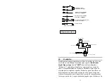
MODE= MODO 


Prog= Prog 


Time= Tiempo 


Counter= Contador 


POWER= ENERGÍA 


SET= AJUSTE 

  = Presione y 
luego libere 
 
 = Mantenga 
presionado por 
aproximadament
e 2 segundos y 
libere 
 
 =


Mantenga 

presionado por 
aproximadament
e 4 segundos y 
libere


Normal Operation=  
Operación normal 
 
TIMED MODE

MODO DE TIEMPO 


Incremental Mode=


MODO ACUMULADO 


OFF= APAG 
 
MANUAL MODE
=


MODO MANUAL 


Setup= Configuración 


Time setting in 
CONTINUE mode
 = 
Ajuste de tiempo en 
modo de TIEMPO 
 
SETUP MODE

MODO DE AJUSTE 


TIME SETTING
AJUSTE DE HORA 


Save and Exit…= 
Guardar y salir… 


COUNTER RESET
REINICIAR 
CONTADOR


Power ON/OFF

 =  

Encendido/Apagado 


Change Mode

 = 

Cambiar de Modo 

Summary of Contents for 883976

Page 1: ...Manual Loctite Digital Syringe Dispenser Part Number 883976 Benutzerhandbuch Loctite Digitales Kartuschendosiergerät Artikelnummer 883976 Manual de operación Loctite Dosificador digital tipo jeringa Número de parte 883976 ...

Page 2: ...ption 4 3 Technical Data 6 4 Installation 6 5 Operation 7 5 1 Set up Instructions Manual Mode 5 2 Dispense Cycle Setting Time Mode Incremental Mode with Teach Function Cycle Counter Reset 6 Troubleshooting 10 7 Maintenance Operational Tips 11 8 Accessories and Spare Parts 11 9 I O Configuration Pneumatic Diagram 12 10 Warranty 13 11 Declaration of Conformity 15 ...

Page 3: ...l as for service activities 1 2 For Your Safety For safe and successful operation of the unit read these instructions completely If the instructions are not observed the manufacturer can assume no responsibility Do not operate the unit in excess of rated capacities Do not use the unit to dispense flammable or corrosive fluids Do not use in wet or exposed environments Observe general safety regulat...

Page 4: ...ter 1 Dual Unit Stacking Lock Pin 8900574 1 Air line Support Mast 8900575 1 Needle Sample Kit 1 Inlet Air Hose 6mm OD x 6ft Fitting Kit 902523 2 Description The Loctite Digital Syringe Dispenser 883976 is semi automatic dispensing system designed for adhesives and fluids packaged in syringe barrels The unit has digital timing control with decimal control to 001 seconds for increased precision over...

Page 5: ...ton 11 Power Receptacle 4 Display 12 I O Connection 5 Air Pressure Gauge 13 Exhaust Port 6 Air Pressure Regulator 14 Air Inlet 7 Pulsed Air Outlet 15 Cord Lock 8 Vacuum Control 8 1 3 2 5 4 14 15 10 12 13 11 9 6 7 Digital Syringe Dispenser S N C Please refer to the instruction CAUTION www equipment loctite com manual before installation MADE IN CHINA Sicherheit geprufte 10W 100PSI Pr oduction m oni...

Page 6: ...rs Max Cycle Mode Timed Incremental Manual Pollution Degree II Timing Repeat Tolerance 0 001 Installation Category I Cycle Rate 600 cycles min Indoor Use Altitude up to 2 000m 6 562ft LCD 16 X 2 display segments Operating Temperature 0 C to 50 C 32 F to 122 F Storage Temperature 10 C to 60 C 14 F to 140 F 4 Installation Use 5 micron Filter Regulator Loctite 985397 or equivalent for inlet air suppl...

Page 7: ...ated on the Air Pressure Gauge 5 5 1 4 After filling the barrel or using pre packaged adhesive attach the syringe to the syringe adapter Make certain that the syringe locks into place 5 1 5 Connect the plug end of the receiver head assembly to the Air Dispense Outlet 7 5 1 6 If vacuum suck back is needed rotate the Vacuum Regulator 8 counter clockwise until the desired vacuum pressure is obtained ...

Page 8: ...ed press and hold the Set button 3 for two seconds to save the data 5 2 2 Setting the Timer in the Incremental Mode Setting the timer from the Incremental mode Teach Mode is helpful in determining dispense time required when dispense output is unknown The timer will continue to accumulate time as long as the foot pedal is depressed allowing the user to teach the unit the exact time needed 5 2 2 1 ...

Page 9: ...ill first show Saving Data but continue holding till the cycle counter resets to 00000 Fig 5 1 Setup TIMED MODE P1 2 250 00004 SETUP MODE P1 00004 SETUP MODE P1 00004 Save and Exit SETUP MODE P1 00004 SETUP MODE P1 00004 SETUP MODE P1 00004 SETUP MODE P1 00004 SETUP MODE P1 00004 SETUP MODE P1 00004 TIMED MODE P1 2 251 00004 TIMED MODE P1 2 251 00000 2 250 2 2 250 2 2 250 2 2 250 2 2 251 2 2 250 2...

Page 10: ...move cover and check for broken wires or loose connections Replace solenoid Replace PC board System will not pressurize Insufficient air pressure Air hoses not plugged in Regulator defective Increase air supply pressure Check connection Replace regulator System will not pull vacuum Vacuum setting is too low Defective solenoid Defective vacuum venturi Defective vacuum needle valve Increase vacuum s...

Page 11: ...an and dry 2 When not in use turn vacuum off or disconnect air supply to unit Failure to do so could result in adhesive being pulled back into the unit and rendering it non functional 3 Avoid turning barrels upside down or laying barrel so that material may run through airline to internal components 4 Avoid connecting air supply exceeding 100 psi 6 9 bars 5 Use only Amyl Alcohol to clean outside s...

Page 12: ...or drive any other operations that need to be tied to the completion of the dispense cycle Upon closure end of dispense cycle power from an external source is allowed to pass through the circuit to operate a 5 to 24 VDC load Power consumption must not exceed 250 mA The load could be a relay solenoid counter LED or any device that will operate within a 5 to 24 VDC range and a maximum of 250 mA To i...

Page 13: ...scovered and in any event within 12 months after the delivery of the Products to the purchaser This warranty does not apply to perishable items such as but not limited to o rings seals washers filters lights etc No such claim shall be allowed in respect of products which have been neglected or improperly stored transported handled installed connected operated used or maintained In the event of una...

Page 14: ...ASER THIS SECTION SETS FORTH EXCLUSIVELY ALL OF LIABILITY FOR HENKEL TO THE PURCHASER IN CONTRACT IN TORT OR OTHERWISE IN THE EVENT OF DEFECTIVE PRODUCTS WITHOUT LIMITATION OF THE FOREGOING TO THE FULLEST EXTENT POSSIBLE UNDER APPLICABLE LAWS HENKEL EXPRESSLY DISCLAIMS ANY LIABILITY WHATSOEVER FOR ANY DAMAGES INCURRED DIRECTLY OR INDIRECTLY IN CONNECTION WITH THE SALE OR USE OF OR OTHERWISE IN CON...

Page 15: ...tage Directive by the application of the following standard IEC61010 1 2001 2nd Edition Complies to RoHS Directive 2002 95 EC given by The European Parliament and The Council of 27 January 2003 on the restriction of the use of certain hazardous substances in electrical and electronic equipment Complies to European Waste Electrical and Electronic Equipment WEEE Directive 2002 96 EC Meets the requir...

Page 16: ...Corporation Engineering Adhesives USA Canada Mexico Henkel Corporation One Henkel Way Rocky Hill CT 06067 3910 Henkel Canada Corporation 2515 Meadowpine Boulevard Mississauga Ontario L5N 6C3 Canada Henkel Capital S A de C V Blvd Magnocentro No8 Piso 2 Interlomas 52760 Huixquilucan Edo de Mexico For all world wide locations Visit www loctite com For Equipment in North America visit www equipment lo...

Page 17: ...3 Technische Daten 7 4 Installation 7 5 Betrieb 8 5 1 Setup Anleitung Manueller Modus 5 2 Einstellen des Dosierzyklus Zeitgesteuerter Modus Inkremental Modus mit Teach Funktion Rücksetzen des Zyklenzählers 6 Fehlerbeseitigung 12 7 Wartungs und Betriebshinweise 13 8 Zubehör und Ersatzteile 14 9 E A Konfiguration und Pneumatikschaltplan 14 10 Garantie 16 11 Konformitätserklärung 18 ...

Page 18: ...treiber des Gerätes oder andere Personen vor Verletzungen Lebensgefahr oder Sachschäden schützen Achtung Hebt hervor was getan oder unterlassen werden muss um das Gerät oder andere Sachwerte nicht zu beschädigen Hinweis Gibt Empfehlungen zum besseren Handhaben des Gerätes bei Bedien und Einstellvorgängen sowie Wartungs und Pflegearbeiten ...

Page 19: ...benen maximalen Nennleistung betreiben Das Gerät nicht zum Dosieren von brennbaren oder ätzenden Flüssigkeiten verwenden Nicht an Nässe aussetzen oder im Freien verwenden Bei der Handhabung von Chemikalien wie z B Loctite Kleb und Dichtstoffen sind die allgemein gültigen Sicherheitsregeln zu befolgen Die im Sicherheitsdatenblatt SDB angegebenen Herstelleranweisungen sind zu beachten Das Gerät muss...

Page 20: ...rden Schadensforderungen müssen vom Empfänger an das Transportunternehmen eingereicht werden Auch der Hersteller sollte darüber informiert werden 1 4 Lieferumfang 1 Digitales Kartuschendosiergerät 883976 1 Universalnetzkabel mit Adapter 902520 1 Fußschalter 902521 1 Kartuschenständer 901459 1 10 ml und 1 30 ml Luftleitungsadapter 1 Sperrstift für die Stapelung von zwei Geräten 1 Luftschlauchträger...

Page 21: ...n Luftleitungsadapter sorgt der einstellbare Druckregler durch die Abgabe von geregelten Druckluftimpulsen für eine kontrollierte Dosierung des Klebstoffs Weitere Merkmale Vakuum Zurücksaugung für eine effektive Kontrolle von Nachtropfen Zeitgesteuerter oder Inkremental Betrieb der Klebstoff kann auf einmal oder schrittweise aufgetragen werden Praktischer Teach Modus hilft bei der Bestimmung der n...

Page 22: ...umregler 8 1 3 2 5 4 14 15 10 12 13 11 9 6 7 Digital Syringe Dispenser S N C Please refer to the instruction CAUTION www equipment loctite com manual before installation MADE IN CHINA Sicherheit geprufte 10W 100PSI Pr oduction m onitor ed S a f ety S V T tested U P R O D U C TS ER V I C E US NRTL V U SUD T Item 98666 24V Corporation Contact Locations For North America Henkel Corporation One Henkel...

Page 23: ...schmutzungsgrad II Wiederholgenau igkeit der Zeitsteuerung 0 001 Installationskategorie I Zyklusgeschwin digkeit 600 Zyklen Minute Nur im Gebäude verwenden Höhenlage bis zu 2 000 m LCD 2 Zeilen mit je 16 Zeichen Betriebstemperatur 0 C bis 50 C Temperaturberei ch für die Aufbewahrung 10 C bis 60 C 4 Installation Für den Lufteinlass muss ein 5 µm Filter Regler Loctite 985397 oder gleichwertig verwen...

Page 24: ...manueller Modus erscheint 5 1 3 Drehen Sie den Druckluftreglerknopf 6 bis der gewünschte Druck am Druckluftmesser 5 angezeigt ist 5 1 4 Füllen Sie die Kartusche oder verwenden Sie eine vorgefüllte Klebstoffkartusche und bringen Sie diese am Kartuschenadapter an Stellen Sie sicher dass die Kartusche einrastet 5 1 5 Verbinden Sie den Stecker des Kartuschenadapters mit dem Dosierausgang 7 5 1 6 Zum Z...

Page 25: ...e gewünschte Zeit einzustellen 5 2 2 3 Drücken Sie die Tasten und um jede Ziffer zu erhöhen oder zu verringern Eine Überschreitung von Null ist mit keiner dieser Tasten möglich Die Mindestdosierzeit ist 00 020 Sekunden 5 2 2 4 Wenn die gewünschte Zeit eingestellt ist halten Sie die Set Taste 3 zwei Sekunden lang gedrückt um die Daten zu speichern 5 2 2 Einstellen der Zeitschaltuhr im Inkremental M...

Page 26: ... die Wiederholung dieses neuen Zeitzyklus eingestellt 5 2 4 Rücksetzen des Zyklenzählers Der Zyklenzähler erfasst die Anzahl der aktivierten automatischen Dosierzyklen Bis zu 65 535 Zyklen können erfasst werden Die Zählung wird unten rechts auf der LCD Anzeige angezeigt Rücksetzen des Zählers 5 2 4 1 Halten Sie die Set Taste 3 zwei Sekunden lang gedrückt um in den Setup Modus zu wechseln 5 2 4 2 U...

Page 27: ...mately 2 seconds then release 00004 Power ON OFF TIMED MODE P1 2 250 OFF Change Mode MANUAL MODE TIMED MODE INCREMENTAL MODE P1 2 250 P1 2 250 00004 00004 MODE MODUS Prog Prog Time Zeit Counter Zähler POWER ENERGIE SET SET Drücken und loslassen Drücken ca 2 Sekunden gedrückt halten dann loslassen Drücken ca 4 Sekunden gedrückt halten dann loslassen Normail Operation Normaler Betrieb TIMED MODE ZEI...

Page 28: ...en und Luftversorgung trennen Abdeckung abnehmen und nach beschädigten Kabeln und losen Anschlüssen suchen Magnet ersetzen Schaltkarte ersetzen Kein Druckaufbau im System Ungenügender Luftdruck Luftschläuche nicht angeschlossen Defekter Regler Luftdruck erhöhen Anschluss überprüfen Regler ersetzen System zieht kein Rückhaltevakuu m Vakuum zu niedrig eingestellt Defekter Magnet Defekte Vakuumdüse D...

Page 29: ...freien Betriebs sollten die folgenden Empfehlungen beachtet werden 1 Die zugeführte Luft muss sauber und trocken sein 2 Wenn nicht im Gebrauch drehen Vakuum ab oder trennen Luftversorgung an die Einheit Misserfolg so zu tun konnte auf Bindemittel hinauslaufen das in die Einheit zurückgezogen wird und es nichtfunktionell macht 3 Die Kartuschen Zylinder sollten nicht umgedreht und nicht so hingelegt...

Page 30: ... und bleibt bis zum nächsten Dosierzyklus geschlossen Dieser Schaltkreis kann für die Signalisierung eines Hostrechners zum Starten eines anderen in Reihe angeschlossenen Gerätes oder zum Ansteuern von anderen mit der Fertigstellung des Dosierzyklus verbundenen Funktionen verwendet werden Nach dem Schließen des Kreises Ende des Dosierzyklus kann Strom von einer externen Quelle durch diesen Kreis g...

Page 31: ...Zyklus MASSE Ende des Zyklus OFFEN Während des Zyklus MASSE Ende des Zyklus OFFEN Beginn eines Dosierzyklus mit Spannung PIN 5 Pin 7 8 und 9 frei PIN 5 PIN 6 Chassiserdung PIN 3 PIN 2 PIN 1 PIN 4 5 24 V Gleichstrom 3 2 1 LUFTEINLASS LUFTVERTIELER DRUCKREGLER NADELVENTIL LUFTAUSLASS MAGNETVENTIL ...

Page 32: ... innerhalb von zwölf 12 Monaten nach Auslieferung des Produktes an den Käufer schriftlich gemeldet werden Diese Gewährleistung gilt nicht für Verschleißteile u a O Ringe Dichtungen Unterlegscheiben Filter Lampen usw Ausgeschlossen hiervon sind Produkte die vernachlässigt oder falsch gelagert transportiert gehandhabt angeschlossen betrieben verwendet oder gewartet wurden Des Weiteren sind Produkte ...

Page 33: ... ABSCHNITT UMFASST DIE GESAMTE HAFTUNG VON HENKEL GEGENÜBER DEM KÄUFER IM FALL VON DEFEKTEN PRODUKTEN OB UNTER EINEM VERTRAG AUS UNERLAUBTER HANDLUNG ODER ANDERWEITIG OHNE EINSCHRÄNKUNG DES VORSTEHENDEN UND IN VOLLEM UNTER DEM ANWENDBAREN RECHT ZULÄSSIGEN UMFANG LEHNT HENKEL AUSDRÜCKLICH JEGLICHE HAFTUNG FÜR SCHÄDEN AB DIE DIREKT ODER INDIREKT IN VERBINDUNG MIT DEM VERKAUF ODER DER VERWENDUNG ODER...

Page 34: ...pannung 72 23 EWG unter Anwendung folgender Norm IEC61010 1 2001 2 Ausgabe Erfüllt die Richtlinie zur Beschränkung der Verwendung bestimmter gefährlicher Stoffe in Elektro und Elektronikgeräten 2002 95 EWG des Europäischen Parlaments und des Rates vom 27 Januar 2003 Erfüllt die EG Richtlinie über Elektro und Elektronik Altgeräte WEEE 2002 96 EWG Erfüllt die Anforderungen des deutschen Geräte und P...

Page 35: ...SA Canada Mexico Henkel Corporation One Henkel Way Rocky Hill CT 06067 3910 Henkel Canada Corporation 2515 Meadowpine Boulevard Mississauga Ontario L5N 6C3 Canada Henkel Capital S A de C V Blvd Magnocentro No8 Piso 2 Interlomas 52760 Huixquilucan Edo de Mexico Internationale Standorte finden Sie unter www loctite com Für in Nordamerika bestimmte Geräte besuchen www equipment loctite com ...

Page 36: ...6 5 Operación 6 5 1 Instrucciones para configuración Modo manual 5 2 Configuración del ciclo de dosificación Modo de tiempo Modo de acumulación con función de aprendizaje Reinicialización del contador de ciclos 6 Solución de problemas 10 7 Consejos para el mantenimiento y la operación 11 8 Refacciones y accesorios 12 9 Configuración de E S y diagrama neumático 12 10 Garantía 14 11 Declaración de c...

Page 37: ...ad Para una operación segura y adecuada de la unidad lea todo el instructivo Si no se acatan las instrucciones el fabricante no podrá asumir ninguna responsabilidad No haga funcionar la unidad por encima de sus capacidades nominales No utilice la unidad para dosificar líquidos inflamables o corrosivos No la utilice en ambientes húmedos o expuestos Obedezca las normas generales de seguridad y prote...

Page 38: ...iones en caso de daños deben hacerse por el consignatario al transportista y deberán ser reportadas al fabricante 1 4 Artículos suministrados 1 Dosificador digital tipo jeringa 883976 1 Cable universal de corriente y adaptador 902520 1 Interruptor de pedal 902521 1 Soporte para la jeringa 901459 Adaptador de línea de aire de 1 10ml y 1 30ml 1 Pasador de seguridad doble de unidad 1 Mástil de soport...

Page 39: ...a permitir que el adhesivo sea aplicado de una sola vez o de manera incremental Práctico Modo de aprendizaje para ayudar a determinar el tiempo requerido cuando no se conoce la cantidad a dosificar La opción de contador de ciclo se muestra claramente en la pantalla de cristal líquido La unidad puede además integrarse a la programación de PLC para facilitar una operación continua 2 3 Descripción de...

Page 40: ...e contaminación II Tolerancia de tiempo de repetición 0 001 Categoría de instalación I Velocidad de ciclo 600 ciclos min Uso en interiores Altitud hasta 2000 m 6562 pies LCD Segmentos de pantalla de 16 x 2 Temperatura de operación De 0 C a 50 C de 0 00 C a 50 00 C Temperatura de almacenamiento De 10 C a 60 C de 14 F a 140 F Elementos Descripción Elementos Descripción 1 Botón de encendido 9 Soporte...

Page 41: ...camente para arranque y purga mediante una aguja dosificadora La unidad viene pre configurada con un tiempo de dosificaciòn de 0 1 segundos El modo manual no funcionará a menos que se haya ajustado la hora en la pantalla de tiempo El ajuste de tiempo a las 00 000 no permitirá que la unidad dosifique en modo manual 5 1 1 Encienda la unidad presionando el botón de encendido 1 5 1 2 Presione el botón...

Page 42: ...5 1 Presione el botón de Modo 2 para seleccionar Modo por tiempo o Modo acumulado Modo por tiempo Permite a la unidad dosificar durante la cantidad de tiempo fijada en el cronómetro cuando se activa el pedal Modo acumulado Permite a la unidad dosificar en tanto el pedal esté presionado y continuará hasta que se haya agotado el tiempo fijado Esto permite que una cantidad predefinida de producto se ...

Page 43: ...acumulado mantenga presionado el botón de ajuste 3 para ingresar al Modo de aprendizaje La unidad mostrará Ajuste pero la hora se mostrará como 0 000 en la pantalla LCD 5 2 4 4 Mantenga presionado el pedal Se dosificará el producto y se acumulará el tiempo Continue liberando y presionando el pedal interruptor hasta que se haya dosificado la cantidad deseada 5 2 4 5 Mantenga presionado el botón de ...

Page 44: ... 2 251 Save and Exit 2 2 251 TIME SETTING COUNTER RESET Time setting in TIMED mode Normal Operation Press and hold for approximately 4 seconds then release SET Counter POWER Prog MODE MODE Time Press then release Press and hold for approximately 2 seconds then release 00004 Power ON OFF TIMED MODE P1 2 250 OFF Change Mode MANUAL MODE TIMED MODE INCREMENTAL MODE P1 2 250 P1 2 250 00004 00004 MODE M...

Page 45: ...tire la cubierta y busque cables rotos o sueltos Reemplace el solenoide Reemplace la tarjeta de PC El sistema no acumula presión Presión de aire insuficiente Las mangueras de aire no están conectadas Falla del regulador Aumente la presión del suministro de aire Verifique la conexión Reemplace el regulador El sistema no extrae el vacío El ajuste del vacío es muy bajo Solenoide con fallas Falla del ...

Page 46: ...ia deben seguirse las recomendaciones detalladas a continuación 1 Asegúrese que el suministro de aire esté limpio y seco 2 When not in gasta turn vacío off ahora disconnect aire supply to une Failure to do so could result in adhesive being pulled back into the une and rendering it no functional 3 Evite voltear los barriles o dejarlos acostados de modo que el material pudiese penetrar por la línea ...

Page 47: ...l ciclo de dosificación un circuito colector se cierra y permanece cerrado hasta el siguiente ciclo de dosificación Puede usarse este circuito para regresar la señal a una computadora anfitriona arrancar otro dispositivo conectado en secuencia o controlar cualesquiera otra operación que necesite ser ligada a la terminación del ciclo de dosificación Al cerrarse fin del ciclo de dosificación se perm...

Page 48: ...muestren ser defectuosos en sus materiales o mano de obra o para otorgar un crédito al comprador por el importe del precio de compra menos los cargos por envío y seguro que serán pagados por el usuario La Diagrama neumático Para iniciar ciclo de dosificación con cierre de contacto Durante el ciclo TIERRA Fin de ciclo ABIERTO Durante el ciclo TIERRA Fin de ciclo ABIERTO Para iniciar ciclo de dosifi...

Page 49: ...os Productos incluyendo el uso de cualesquiera productos partes o accesorios no fabricados por Henkel para ser utilizados en conexión con los Productos cuando los productos partes o accesorios estén disponibles de Henkel no procederán las reclamaciones No deberá devolverse ningún producto a Henkel bajo ninguna circunstancia sin antes obtener la aprobación por escrito de Henkel Los productos deben ...

Page 50: ...ASTA LA MÁXIMA EXTENSIÓN POSIBLE BAJO LAS LEYES APLICABLES HENKEL EXPRESAMENTE SE LIBERA DE CUALQUIER RESPONSABILIDAD POR LOS DAÑOS OCURRIDOS COMO CONSECUENCIA DIRECTA O INDIRECTA CON RELACIÓN A LA VENTA USO O CUALQUIER OTRA ACCIÓN CON RESPECTO DE LOS PRODUCTOS INCLUYENDO ENTRE OTRAS LA PÉRDIDA DE GANANCIAS ASÍ COMO LO DAÑOS PROVOCADOS INDIRECTAMENTE O A CONSECUENCIA DE NEGLIGENCIA DE HENKEL O TER...

Page 51: ... bajo mediante la aplicación de la siguiente norma IEC61010 1 2001 2a Edición Cumple con la norma RoHS número 2002 95 EC dada por el Parlamento Europeo y el Consejo con fecha 27 de enero de 2003 sobre la restrición en el uso de ciertas sustancias de riesgo en el equipo eléctrico y electrónico Cumple con la directriz europea sobre de desechos de equipo eléctrico y electrónico WEEE número 2002 96 EC...

Page 52: ...ring Adhesives EUA Canadá México Henkel Corporation One Henkel Way Rocky Hill CT 06067 3910 Henkel Canada Corporation 2515 Meadowpine Boulevard Mississauga Ontario L5N 6C3 Canada Henkel Capital S A de C V Blvd Magnocentro No8 Piso 2 Interlomas 52760 Huixquilucan Edo de Mexico Para conocer nuestras ubicaciones en todo el mundo visite www loctite com Para Equipo en América del Norte visite www equip...

Reviews: