


Gocator 200 Series and Light Bar Quick Start Guide
12
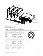
Function
Pin
Lead Color on
Standard Cordsets
Lead Color on
High Flex Cordsets
Ethernet MX3-
S
White/Blue
White/Blue
Ethernet MX3+
R
Blue
Blue
Ethernet MX4+
T
White/Brown
White/Brown
Ethernet MX4-
U
Brown
Brown
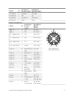
Function
Pin
Lead Color on
Standard
Cordset
Lead Color on
High Flex
Cordset
Tri
D
Grey
Blue / Red
View: Looking into the
connector
on
the sensor
Trigger_in-
H
Pink
Blue / Black
Out_1+ (Digital Output
0)
N
Red
Brown / Red
Out_1- (Digital Output
0)
O
Blue
Brown / Black
Out_2+ (Digital Output
1)
S
Tan
Green / Red
Out_2- (Digital Output
1)
T
Orange
Green / Black
En
M
White / Brown &
Black
Pink / Red
Encoder_A-
U
Brown / Black
Pink / Black
En
I
Black
Yellow / Red
Encoder_B-
K
Violet
Yellow / Black
En
A
White / Green &
Black
White / Red
Encoder_Z-
L
Green / Black
White / Black
Ser
B
White
Purple / Red
Serial_out-
C
Brown
Purple / Black
E
Blue / Black
Red
G
White / Blue &
Black
Black
Reserved
P
Green
Gray / Red
Reserved
F
Yellow & Maroon
/ White
Gray / Black
& Orange / Black
Reserved
R
Maroon
(not connected)
Orange / Red
(not connected)
Gocator I/O Connector Pins