


www.lkarmatur.se | www.lkarmatur.com | www.lkarmatur.de
ENG
| Instruction Manual
1
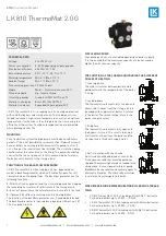
LK 810 ThermoMat 2.0 G
TECHNICAL DATA
Voltage
230 VAC 50 Hz
Power consumption
5-52 W, depending on pump speed
Max. boiler efficiency
65 kW at 20 °C ΔT
Return temperature
55 °C, 60 °C, 65 °C or 70 °C
Working temperature
Min. 5 °C/Max. 110 °C
Ambient temp.
Min. 0 °C/Max. 70 °C
Max. working pressure 0.6 MPa (6 bar)
Media
Water - Glycol mixture max. 50%
Thread standard
Rp - female thread
Circulating pumps
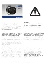
Grundfos UPM3 AUTO L xx-70
Material, valve body
Brass EN 1982 CB753S
Material, insulation
Expanded Polypropylene EPP
LK 810 ThermoMat 2.0 G is a loading unit for heating applications
with solid fuel boilers and storage tanks. The loading unit is in-
tended to ensure a high return temperature as well as an optimal
temperature stratification in the storage tank, thus increasing the
efficiency of the system. Tarring and condensation are prevented
which prolongs boiler life.
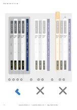
CIRCULATING PUMP
Four pump positions are available depending on boiler capacity.
It is to be noted that the maximum capacity of a boiler may be
higher than its nominal capacity.
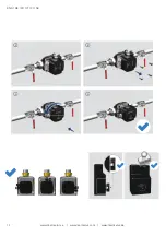
FUNCTION OF THE BACKFLOW PREVENTER
LK 810 ThermoMat 2.0 G Eco loading unit has, depending on
model, a backflow preventer which automatically opens for self-
circulation when the pump stops. The backflow preventer has the
following functions:
1.
After the fire has gone out and the circulating pump has stopped
the remaining hot water will selfcirculate to the storage tank.
2.
In case of power failure the hot water will self-circulate to the tank.
3.
It prevents backflow from storage tank to heating boiler.
The function of the backflow preventer can, if needed, be blocked.
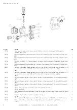
The backflow preventer is then replaced by a plug LKA art.no: 187
022. See page 9, part 8.
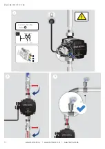
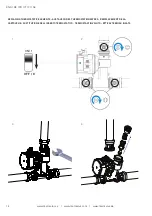
MOUNTING
For a trouble free system the piping work must be done without air
pockets. If this is not possible the system must be fitted with air vents.
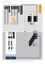
Several boilers have integrated thermostats for pump control. If
not, a flue gas thermostat must be installed. The circulation pump
should start at the same time as the firing. The pump should stop
soon after the fire has gone out to let the remaining hot water in
the boiler self-circulate to the storage tank.
PIPE DIMENSIONING BETWEEN HEATING BOILER AND STORAGE
TANK:
•
LK 810 ThermoMat 2.0 G Eco loading unit with Rp 1” ball valve.
For heating boilers up to 40 kW ….. DN 25
•
LK 810 ThermoMat 2.0 G Eco loading unit with 28 mm ball valves.
For heating boilers up to 40 kW …. CU 28
•
LK 810 ThermoMat 2.0 G Eco loading unit with Rp 1¼“ ball valves.
For heating boilers up to 65 kW …. DN 32
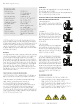
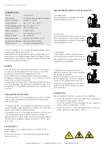
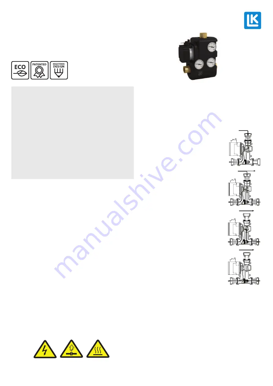
1. Heat up phase
The water circulates between boiler and lo-
ading unit while the temperature of the boiler
is rising.
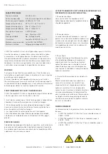
2. Loading phase
The thermostatic element starts to open and
allows return water from the storage tank to
be mixed with supply water before it returns
to the boiler. The return temperature to the
boiler is kept constant.
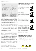
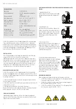
3. End phase
The thermostatic element is fully open and
the bypass is closed. This results in an opti-
mal transfer of heat from the boiler and the
storage tank is filled with supply water.
4. Self-circulation with check valve
Self-circulation will be obtained as soon as the
fire has gone out and the circulating pump has
stopped. The remaining hot water is loaded to the
storage tank. In case of power failure or pump
breakdown the check valve automatically opens to
allow self-circulation. The check valve also stops
recirculation from storage tank to boiler.
THE FUNCTION OF THE LOADING UNIT DURING THE DIFFERENT
PHASES OF HEATING:


