6-7
January 24, 2017
Structure Function Principle
CLG835H
Engine hood
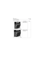
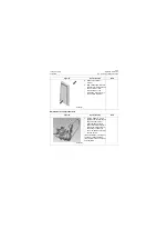
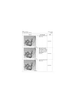
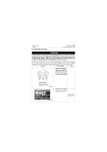
Lifting mechanism of engine hood
torsion bar
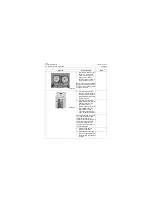
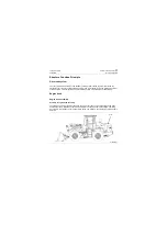
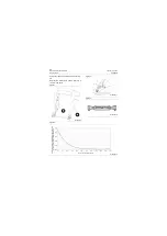
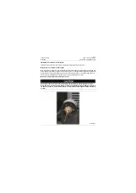
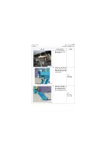
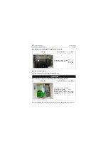
1. Overview-components and position
The components and position of lifting mecha-
nism of engine hood torsion bar used in com-
plete machine are as shown in the figure below
and mainly composed of rear cover, bracket and
torsion spring. The torsion bar-assist type turn-
over mechanism involved in the mechanism is
able to solve effectively the problem of difficult
closing caused by large turning torque during the
turning of torsion bar turnover mechanism, and
the provided torsion bar-assist type turnover
mechanism includes the base and the turning
parts hinged on the base. The base is provided
with torsion bar, which is mutual parallel to the
center of rotation of mentioned turning parts with
its one end permanently connected to the base,
while the other end rotates relative to base and
permanently connected to lever arm; moreover, it
includes link, one end of which is hinged with
lever arm, while the other end hinged with turn-
ing parts. The base, lever arm, link and turning
parts in the torsion bar turnover mechanism
forms four-bar mechanism.
2. Overview - part working principle
When the torsion bar-assist type turnover mech-
anism used in this model is used on the engine
hood of machine,the base acts as frame and the
turning parts act as hood; the base, lever arm,
link and turning parts forms four-bar mechanism;
the distance between point A and C increases
gradually to improve the torque in the later stage
during the turning process for opening the hood;
while the distance between point A and C
decreases gradually to reduce the torque of the
torsion bar against the turning part, i.e reducing
the tensile force necessary for closing the engine
hood to make easy closing of hood during the
turning process for closing the hood.
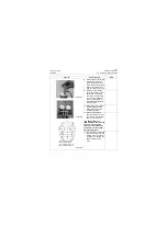
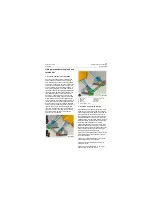
Figure 1 is the structure diagram that the torsion
bar-assist type turnover mechanism is used on
the hood of machine;
Figure 2 is the structure diagram of the torsion
bar-assist type turnover mechanism;
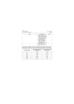
Figure 3 is the structure diagram of link with
adjustable length;
Figure 4 is the relation diagram of rear cover
opening angle vs required torque.
1
2
3
4
5
6
7
8
9
P18C00008
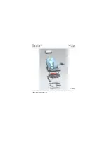
1. Rear cover
2. Bracket
3. Plate
4. Push rod
5. Torsion spring - right
6. Torsion spring - left
7. Bracket
8. Push rod
9. Rod as
P18C00009
9
Summary of Contents for CLG835H
Page 2: ......
Page 4: ...Contents January 24 2017 CLG835H...
Page 6: ...1 2 General Information January 24 2017 CLG835H...
Page 38: ...1 34 Machine Inspection Table January 24 2017 CLG835H...
Page 156: ...3 2 Power Train System January 24 2017 CLG835H...
Page 214: ...3 2 Power Train System January 24 2017 CLG835H...
Page 272: ...3 60 Testing and adjustment January 24 2017 Power Train Test CLG835H...
Page 276: ...4 4 Hydraulic System January 24 2017 CLG835H...
Page 552: ...6 2 Driver s Cab System January 24 2017 CLG835H...
Page 608: ...7 2 Structure January 24 2017 CLG835H...
Page 662: ...8 4 Electrical System January 24 2017 CLG835H...
Page 677: ...8 19 January 24 2017 Structure Function Principle CLG835H Power System P18E00014...


