MAN 4169445
Rev A.
06-2013
Original Language Instructions
LITTLE WONDER
OPERA
T
OR / P
AR
TS MANUAL
®
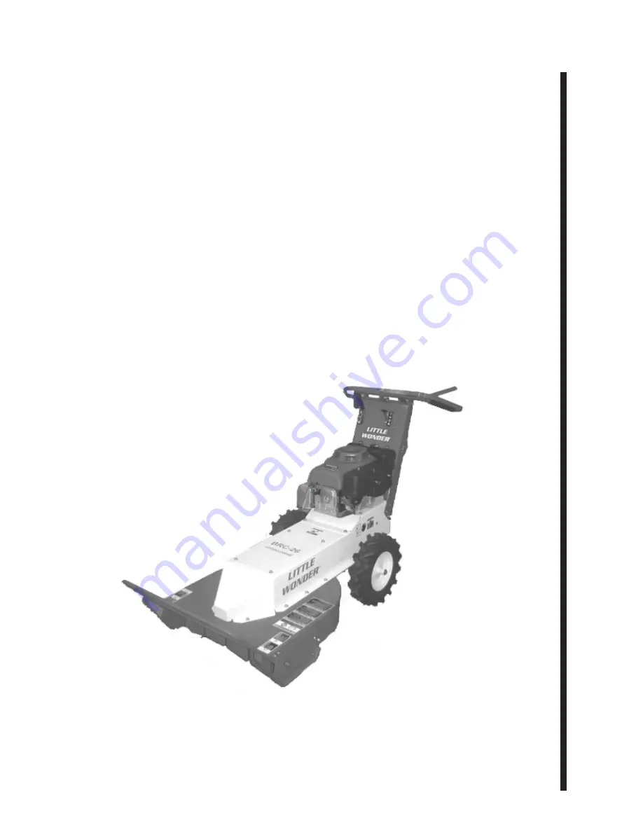
BRC-26 HYDRO
26” LITTLE WONDER BRUSH CUTTER
MODELS:
5126-22-01 HONDA GX390
(S/N 00486 and Above)
5126-32-20 HONDA GX390 HD
(S/N 00107 and Above)
5126-21-03 B&S 12.5


