Lite-Puter DX-1210, User Manual
The Lite-Puter DX-1210 is a cutting-edge lighting control system designed to bring convenience and ease to users. To make the most out of this incredible product, we provide a comprehensive User Manual for free download from our website. Unlock the full potential of DX-1210 with our detailed manual, available at manualshive.com.
Share
Download


Reviews:
No comments
Related manuals for DX-1210

Power Xchange PXCGTS-018
Brand: Ozito Pages: 10

PHSHE 900 B2
Brand: Parkside Pages: 61

Twist 'N Edge 530087611
Brand: Weed Eater Pages: 7

Y2500
Brand: Yard Machines Pages: 12
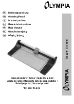
TR 4610
Brand: Olympia Pages: 16

2100586
Brand: Cramer Pages: 151

BlueRazor MST601
Brand: Blaupunkt Pages: 56

SmartHome MTSWD-100-WL
Brand: myTEM Pages: 3

DUH551
Brand: Makita Pages: 92

GT200 Series
Brand: Black & Decker Pages: 40

BESTE625
Brand: Black & Decker Pages: 16

GT524
Brand: Black & Decker Pages: 64

GL600N
Brand: Black & Decker Pages: 22

GL570
Brand: Black & Decker Pages: 50

CHH2220
Brand: Black & Decker Pages: 44

BHT518
Brand: Black & Decker Pages: 12

GT20
Brand: Black & Decker Pages: 80

TRl16
Brand: Black & Decker Pages: 32


