Lippert Components OneControl X1 Oem Installation Manual Download Page 5

Rev: 08.31.20

Page 5

CCD-0002697

Each output used must be assigned and named using the X Series Configurator (Fig. 4) during 

the configuration procedure.

F. 

High Current (HC) Reversing Outputs (Fig. 1, #3, #4 and #5): Connections are available for three 

high current reversing outputs. Each output uses a quick slide connector for Extend and Retract. 

Each output used must be assigned and named using the X Series Configurator (Fig. 4) during 

the configuration procedure.

Wiring

1

2

3

4

5

6

7

8

9

10

11

12

13

14

15

16

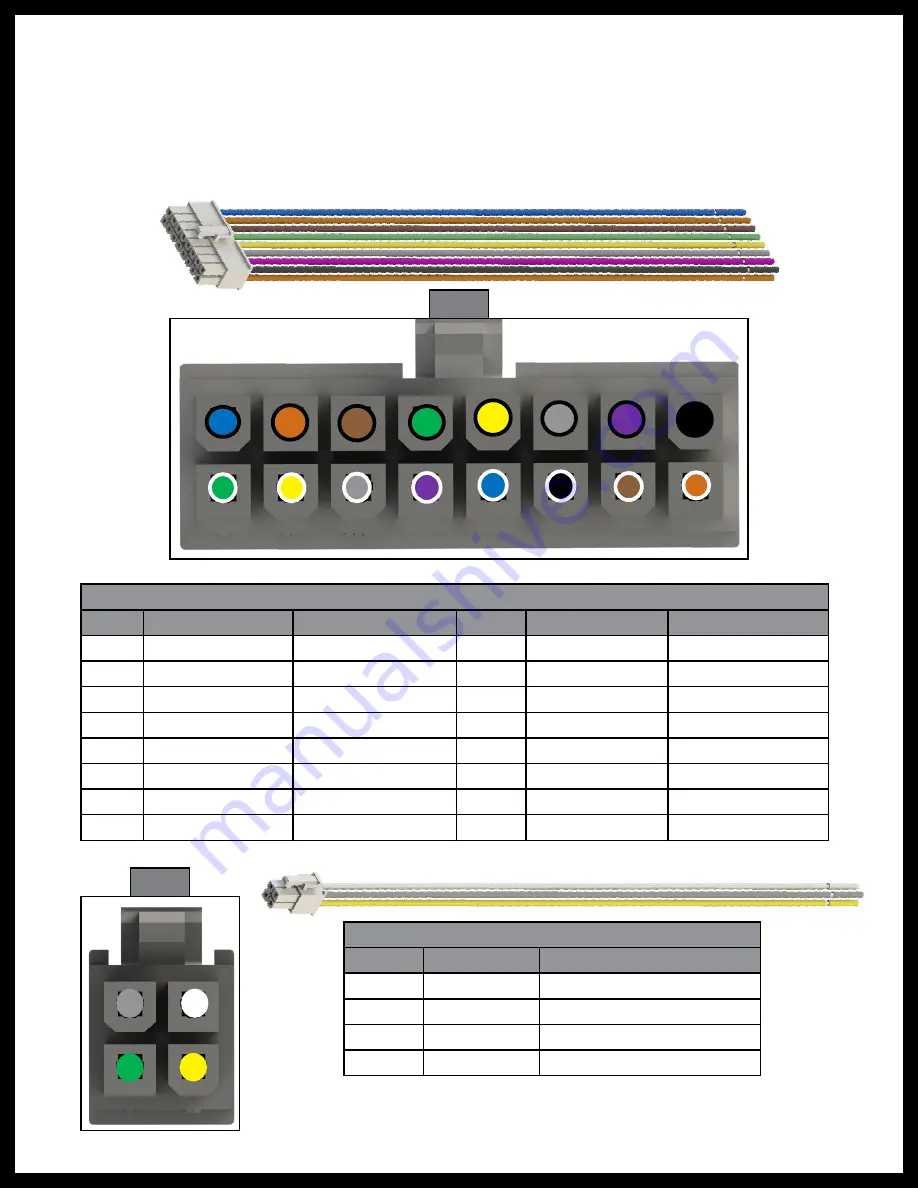
16 Pin Switch Input Harness

Pin

Color

Function

Pin

Color

Function

1

Green/White

Configurable 1

9

Blue/Black

Configurable 9

2

Yellow/White

Configurable 2

10

Orange/Black

Configurable 10

3

Gray/White

Configurable 3

11

Brown/Black

Configurable 11

4

Violet/White

Configurable 4

12

Green/Black

Configurable 12

5

Blue/White

Configurable 5

13

Yellow/Black

Configurable 13

6

Black/White

Configurable 6

14

Gray/Black

Configurable 14

7

Brown/White

Configurable 7

15

Violet/Black

Configurable 15

8

Orange/White

Configurable 8

16

Black

Configurable 16

1

2

3

4

5A Latching Output Harness

Pin

Color

Function*

1

Green

2

Yellow

3

Gray 

4

White

Fig. 2 

Fig. 3 

* Output function based on configuration.

See Installation section, step 3D. 

Summary of Contents for OneControl X1

Page 1: ...OneControl X1 Control Board OEM INSTALLATION MANUAL...

Page 2: ...creen icon If the trailer already has a OneControl Touch Panel then the controller can be tied into the OCTP by CAN bus harness The configurator kit supplied to OEMs must be used to program the config...

Page 3: ...rocedure has a safety risk involved and may cause death serious personal injury or severe product and or property damage if not performed safely and within the parameters set forth in this manual Fail...

Page 4: ...are configured to be used with manual switches for both reversing and latching outputs Any one of the inputs can also be configured as a DSI fault input if needed for a gas water heater D Low Current...

Page 5: ...Switch Input Harness Pin Color Function Pin Color Function 1 Green White Configurable 1 9 Blue Black Configurable 9 2 Yellow White Configurable 2 10 Orange Black Configurable 10 3 Gray White Configura...

Page 6: ...pen supplied X Series Configurator box Fig 4 and remove the power cord CAN harness and the power and ground connections Fig 5 2 Plug in the power cord to a power outlet and insert the CAN harness in o...

Page 7: ...screen 7 A warning about entering an Advanced Feature will appear Fig 9 Press YES 8 The configurator screen will appear Fig 10 Latching Relays 1 Scroll down to the Latching Relay section and press UN...

Page 8: ...er replacing Loaded 5 Scroll down to the next field of FUSE TYPE select a fuse and press SET to save the selection Saved Fig 16A will appear in the lower left corner replacing Loaded Note The next opt...

Page 9: ...BRAKE OPERATION MODE 10 Choose one of the options Fig 21 Always or Only with Park Brake On 11 Press SET Fig 21A Saved will replace Loaded on the screen Fig 22A 12 IN MOTION LOCKOUT LEVEL Fig 23 Scroll...

Page 10: ...se one of the options Fig 27 Toggle Switch or Momentary Switch 17 Press SET Fig 27A Saved will replace Loaded on the screen Fig 28A 18 MINIMUM OPERATING VOLTAGE Fig 29 Scroll down to MINIMUM OPERATING...

Page 11: ...ig 33 Not Set 1 to 16 Note Use caution not to assign the same input to multiple outputs 23 Press SET Fig 33A Saved will replace Loaded on the screen Fig 34A 24 DSI FAULT INPUT Fig 35 Scroll down to DS...

Page 12: ...39 Disabled various increments from 1 minute to 1 hour 29 Press SET Fig 39A Saved will replace Loaded on the screen Fig 40A 30 Press the back button at the bottom of the screen Fig 40B to return to t...

Page 13: ...ig 42 Note If more than one device type of the same name is used press INSTANCE Fig 44C to select a number e g Bedroom Slide 1 Bedroom Slide 2 etc 3 Press UNKNOWN under NAME to select device name Fig...

Page 14: ...ly with ignition On 7 Press SET Fig 46A Saved will replace Loaded on the screen Fig 47A 8 PARK BRAKE OPERATION MODE Fig 48 Scroll down to PARK BRAKE OPERATION MODE 9 Choose one of the options Fig 49 A...

Page 15: ...tract allowed 13 Press SET Fig 52A Saved will replace Loaded on the screen Fig 53A 14 MINIMUM OPERATING VOLTAGE Fig 54 Scroll down to MINIMUM OPERATING VOLTAGE 15 Choose one of the options Fig 55 None...

Page 16: ...INPUTS 18 Select the input numbers to be assigned to EXTEND and RETRACT for this output Fig 58 19 Press SET Fig 58A Saved will replace Loaded on the screen Fig 59A 20 CLOUD CAPABILITIES Fig 60 Scroll...

Page 17: ...utton Fig 61B to return to the main configuration screen 24 Configure up to four more pairs of reversing outputs 25 Press the Home button Fig 61C to return to the Home screen 26 The configured options...

Page 18: ...to save or load the configuration Fig 64 Press SAVE Fig 64A Note If the box doesn t pop up automatically it can be accessed by pressing the menu bars in the top left corner beside All Devices Fig 64B...

Page 19: ...box doesn t pop up automatically it can be accessed by pressing the menu bars in the top left corner beside All Devices Fig 70B 3 Wait a few moments while the configuration is loading Fig 71 4 The lo...

Page 20: ...esentative has been provided Any unauthorized use shall void any applicable warranty The information contained in this manual is subject to change without notice and at the sole discretion of LCI Revi...

Reviews: