Lippert Components 799870 Installation And Owner'S Manual Download Page 6

6

lci1.com      


574-537-8900    


Rev: 03.02.21

Ground Control

®

 TT 

Leveling OneControl

® 

Touch Panel 

(3K-5K)


Installation and Owner’s Manual

(For Aftermarket Applications)

CCD-0002700

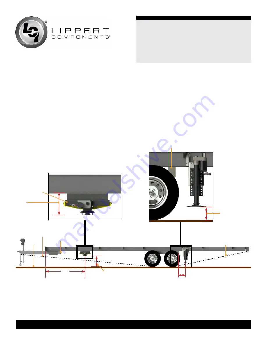
Measuring Departure and 

Approach Angle

Before checking ground clearance make sure the trailer is 

level front-to-back. 
Departure and approach angles are measured by running 

a string line from the meeting point of the tire and ground 

up at an angle to the lowest point on the front or rear of the 

trailer. These string lines are shown as dotted lines 

(Fig.1)

.

Measure from the front of the frame and make a mark at 

60”. This will be the maximum allowable distance for the 

location of the center of the C-Jack footpad. The final 

location should be as close to the draw bar as possible, 

staying within the approach angle 

(Fig.1)

.

Fig.1 

C-jack shown 

for reference 

only to mark

1/2

”  

clearance

above the

string line

is required

departure angle

string line 

ground

approach angle

string line 

draw bar

60”

maximum

distance

12”

maximum

distance

Measure 12” from the center of the rear axle hanger to the 

center of the rear 5K short jack footpad. This will be the 

maximum allowable distance for the location of the center 

of the 5K jack footpad. Make sure the jack footpad is within 

the departure angle 

(Fig.1)

.

NOTE: 

Before checking ground clearance make sure the 

trailer is level front-to-back.

10.5” to 15”

ground clearance

7” minimum

ground clearance

axle hanger

Summary of Contents for 799870

Page 1: ...ket Kit Aftermarket Kit Part Part Description Description 799870 Ground Control TT Leveling OCTP Unhitching from the Tow Vehicle 17 Auto Level 18 Hitch Recognition 18 OneControl Touch Panel Diagram 19...

Page 2: ...Android are trademarks of Google Inc Safety Read and understand all instructions before installing or operating this product Adhere to all safety labels This manual provides general instructions Many...

Page 3: ...WHEN PERFORMING SERVICE OR MAINTENANCE TO THE UNIT OTHER SAFETY EQUIPMENT TO CONSIDER WOULD BE HEARING PROTECTION GLOVES AND POSSIBLY A FULL FACE SHIELD DEPENDING ON THE NATURE OF THE SERVICE MOVING...

Page 4: ...8 and 10 I beam 2 M 333041 Canbus Terminating Resistor 2 Parts List NOTE Part numbers are shown for identification purposes only Not all parts are available for individual sale All parts with a link...

Page 5: ...0 12 AJ 365417 Hex Serrated Flange Nut 3 8 16 12 Callout Part Description Qty N 425585 4 Pin Pigtail Harness 1 O 305115 Hall Effect Right Rear Sensor Harness 1 306298 Hall Effect Left Rear Sensor Harn...

Page 6: ...mum allowable distance for the location of the center of the C Jack footpad The final location should be as close to the draw bar as possible staying within the approach angle Fig 1 Fig 1 C jack shown...

Page 7: ...and make a mark at 60 Fig 1 This will be the maximum allowable distance for the location of the center of the C Jack footpad The final location should be as close to the draw bar Fig 1 as possible sta...

Page 8: ...of the I beam mounting brackets NOTE If there is no mark or hole for the center location on the center tube measure and mark the location Fig 5 Fig 6 B A C C A B A 11 Use the eight pre drilled holes...

Page 9: ...t Jack Installation 1 Measure from the center of the rear axle hanger Fig 9A back 12 maximum distance on the frame and mark the location on the web of the I beam Fig 9B 2 Measure the center location o...

Page 10: ...the compartment where the controller will be mounted NOTE LCI recommends zip tying the harness tight against the rear jack motors to prevent damage to the harness 11 Repeat steps 1 10 for the opposite...

Page 11: ...the 2 pin Deutsch Connector to the Power Tongue Jack wires and run the harness to the compartment where the controller will be mounted See Installing the Controller section 7 Connect the power wire fr...

Page 12: ...jacks as signified by section B in Fig 18 Both the front sensor and the rear sensor must also be mounted in line with the center of the frame as signified by the dotted blue line in Fig 18 The Levelin...

Page 13: ...the trailer Orientation is imperative for the correct operation of the leveling system 2 Attach the sensor Fig 21A to the mounting plate Fig 21B using two 12 x 1 screws Fig 21C Fig 21 NOTE To avoid c...

Page 14: ...nto the open CAN port on the controller See the Wiring Diagram section OneControl Touch Panel Pad Installation OneControl Touch Panel 1 Determine where to mount the OneControl Touch Panel The touch pa...

Page 15: ...unting tabs using the two provided Phillips pan head sheet metal screws Auto Leveling Control Touch Pad 1 Determine where to mount the Auto Leveling Control Touch Pad The touchpad should be mounted on...

Page 16: ...and the Power Tongue Jack will automatically retract NOTE Make sure the leg of the Power Tongue Jack Fig 30A is fully retracted prior to moving the tow vehicle A B C Fig 30 A Unhitching from Tow Vehi...

Page 17: ...ig 31B and C at the same time The green indicator LED Fig 31A will turn on NOTE The touchpad will remain on as long as the user is pressing buttons It will time out after approximately five minutes wi...

Page 18: ...iler will level front to back then side to side G The auto leveling sequence will ground all jacks to make sure all footpads are on the ground H The auto leveling sequence is complete when the indicat...

Page 19: ...ation e g angle jack stroke or software version D Options Icon Press to program zero point wireless configurations E Home Icon Returns screen to home page F Auto Retract Enters Auto Retract mode to re...

Page 20: ...ILL CREATE AN UNSTABLE AND UNSAFE CONDITION OneControl Touch Panel Basic Jack Operation in Standard Mode To reach Standard Mode Fig 32 for leveling 1 Power on the OneControl Touch Panel Fig 32L The to...

Page 21: ...ial frame twist has been relieved 1 Press EXTEND Fig 35F or RETRACT Fig 35E button and FRONT button Fig 35A to operate front jacks 2 Press EXTEND or RETRACT button and REAR button Fig 35C to operate r...

Page 22: ...Panel indicates Auto Level Success NOTE If the auto leveling sequence does not perform as described above locate the OneControl Touch Panel or use the OneControl App to place the system in Manual Mod...

Page 23: ...jack stroke or software version D Options Icon Press to program zero point wireless configurations E Home Icon Returns screen to home page F Auto Retract Enters Auto Retract mode to retract all jacks...

Page 24: ...nd connect to the myRV wireless network NOTE If this is the first time connecting to the myRV wireless network a password will be required The password is located on the trailer s Wi Fi hub Fig 37 Fig...

Page 25: ...g 39A 3 The screen will show the system menu Fig 36 for Standard Mode The Power Tongue Jack can be extended retracted in Standard Mode Front and rear jacks cannot be operated in Standard Mode Fig 39 A...

Page 26: ...n Fig 40C to operate rear jacks 4 Press EXTEND or RETRACT button and LEFT button Fig 40D to operate left jacks NOTE To operate jacks individually press the EXTEND or RETRACT button then press the LEFT...

Page 27: ...istance away from the trailer 2 Power on the OneControl Touch Panel App 3 Press the Leveling icon Fig 39A 4 Press AUTO LEVEL button Fig 36K NOTE Once the automatic leveling cycle has been started it i...

Page 28: ...ing Red Error Refer to OneControl Touch Panel screen or the Leveling App for the specific error then consult the Troubleshooting section to clear the error Error Display in OneControl Touch Panel or O...

Page 29: ...point not set Set zero point LOW VOLTAGE Bad connection or wiring Check wiring repair or replace Discharged or bad battery Test battery voltage under load charge or replace OUT OF STROKE Unsecured sen...

Page 30: ...ration section B Press EXTEND and REAR buttons to extend the rear jacks if required Refer to Operation OneControl Touch Panel and Operation OneControl App sections 5 Press ENTER button to begin auto r...

Page 31: ...Fig 42A NOTE Make sure the leg Fig 41B of the Power Tongue Jack is fully retracted prior to moving the tow vehicle C Jacks Manual Override NOTE For ease of manual override it is recommended to unplug...

Page 32: ...er plug Fig 46A Jack Manual Override Nut Tools needed 3 4 socket wrench 1 Locate the manual override nut Fig 45A 2 Place 3 4 socket wrench over the manual override nut Fig 45A and turn the override nu...

Page 33: ...e double check all connections on the controller jacks and touch panel 2 When calibrating Zero Point the user has full manual control over the jacks See Basic Jack Operation In Manual Mode in the Oper...

Page 34: ...g sensor front leveling sensor harness tongue jack harness front jack harness front left jack controller recommended 50 to 100 amp circuit protection per RVIA standards OEM supplied front right jack r...

Page 35: ...rmance the system requires full battery current and voltage The battery MUST be maintained at full capacity 2 Check the terminals and other connections at the battery the controller and the jacks for...

Page 36: ...mplete document only unless Lippert Components provides explicit consent to distribute individual parts All manual information is subject to change without notice Revised editions will be available fo...

Reviews: