-93-
Display
Press the “Change display” at the bottom of the monitor data display screen for several times to switch to the tim
-
ing waveform display screen.
Control
1) Press [RUN] to start timing waveform measurement at the same time as the normal measurement function
starts. “ ” Is displayed in the upper left of the screen.
2) When the waveform monitor trigger condition is met and the timing waveform sampling is completed,
“ ” At the upper left of the screen disappears.
3) Press [STOP] to stop measurement.
ڦ
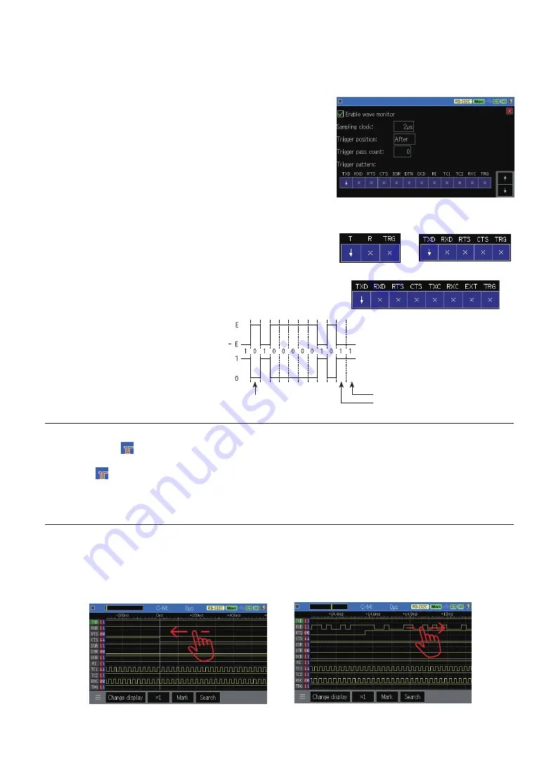
Trigger pattern
Sets the state of the signal line with which it automatically
stops the waveform monitor measurement. The signals that
can be set vary depending on the interface and the option
board being used.
[0]
: 0
[1]
: 1
[END/X]
: X (Don’t care)
[SHIFT]+[0] :↓(Falling edge)
[SHIFT]+[1] :↑(Rising edge)
Be sure to set the edge (↑) (↓) to the trigger condition.
TRG is the external trigger input TRG IN of the TTL port.
ڦ
Scroll the display
Swipe left or right to scroll to the part you want to see.
ڦ
Trigger pass count
Set the number of times (0 to 9999) to ignore the trigger pattern match. When it is 0, the trigger will be estab-
lished at the first trigger pattern match.
When RS-422/485
is selected
When TTL
is selected
When using OP-SB5GL
Display of timing waveform
Waveform of RS-232C
(“A”=41h)
Stop bit
Data bit
Stop bit
Parity bit


