1
dc1792af
DEMO MANUAL DC1792A
Description
LTC2756
Serial 18-Bit SoftSpan I
OUT
DAC
Demonstration circuit 1792A features the LTC2756 18-bit
SoftSpan™, I
OUT
DAC. The digital interface is a simple,
4-wire Serial Peripheral Interface (SPI) interface, aug-
mented with separate
CLEAR
and
LDAC
pins that reset
the output to zero and load the DAC code, respectively.
This device features six output ranges: 0V to 5V, 0V to
10V, ±5V, ±10V, ±2.5V, and –2.5V to 7.5V. These ranges
are programmable through the SPI interface or through
L
, LT, LTC, LTM, µModule, Linear Technology and the Linear logo are registered trademarks
and SoftSpan and QuikEval are trademarks of Linear Technology Corporation. All other
trademarks are the property of their respective owners.
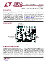
BoarD photo
separate span control pins if SoftSpan operation is not
needed. Voltage input offset and gain adjustment pins
facilitate trimming of residual DC errors without impacting
the excellent temperature stability of this device.
Design files for this circuit board are available at
http://www.linear.com/demo
DAC
OUTPUT
ANALOG POWER SUPPLY
(NORMALLY ±15V)
RIBBON CABLE TO
DC590 CONTROLLER
Connect a low noise ±15V power supply to the AMPV
+
and AMPV
–
turret posts at the left side of the DC1792A
board. Connect J1 to a DC590 USB serial controller us-
ing the supplied 14-conductor ribbon cable. Connect
DC590 to a host PC with a standard USB A/B cable.
Run the evaluation software supplied with the DC590,
or download it from www.linear.com/software. The cor-
rect control panel will be loaded automatically, shown in
Quick start proceDure
Figure 2. The software automatically sets the LTC2756
outputs according to the entries in the control panel. A
square wave option is available to test settling time. MSPAN
jumper should be set to 0 if software span control is desired.
Setting MSPAN high (1) causes the S2, S1, S0 pins to set
the span according to the table printed on the board, and
the corresponding span should be selected in software to
ensure that the calculated DAC code is correct.
Figure 1. Connection Diagram
Downloaded from


