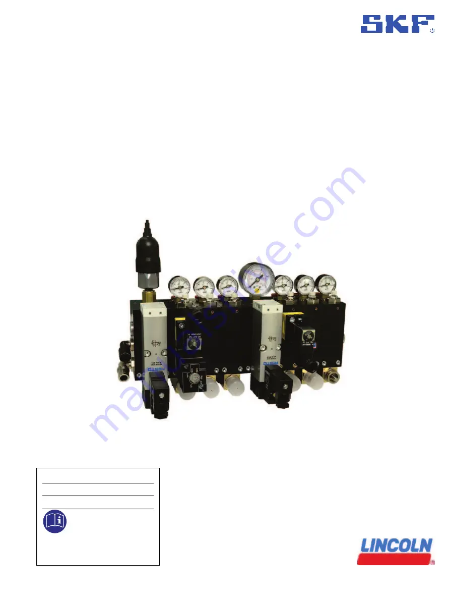
Assembly Instructions
VTEC unit
SKF VectoLub
Date issue:
08-2022
Document No.:
951-130-440
Version :
02
Read manual prior to installation or use of this product. Keep manual nearby for future reference.
Page 1: ...Assembly Instructions VTEC unit SKF VectoLub Date issue 08 2022 Document No 951 130 440 Version 02 Read manual prior to installation or use of this product Keep manual nearby for future reference...
Page 2: ...rporation according to the Supply of Machinery Safety Regulations 2008 No 1597 Annex II The manufacturer hereby declares under sole responsibility that the partly completed machinery complies with the...
Page 3: ...1 Risk of loss of stability no 1 3 2 Risk of break up during operation yes yes 1 3 3 Risks due to falling or ejected objects no 1 3 4 Risks due to surfaces edges or angles yes yes 1 3 5 Risks related...
Page 4: ...e yes yes 1 The product is basically designed for the use of harmless media The operator must check whether the lubricant used has certain hazardous effects e g sensitization If necessary a retention...
Page 5: ...re given on our website www skf com lubrication Training courses In order to provide a maximum of safety and economic viability SKF carries out detailed training courses It is recommended that the tra...
Page 6: ...al data 16 5 Delivery returns storage 18 5 1 Delivery 18 5 2 Return shipment 18 5 3 Storage 18 5 4 Storage temperature range 18 6 Assembly 19 6 1 General 19 6 2 Positioning and installation 19 6 2 1 S...
Page 7: ...ty or malfunctions Illustrations The illustrations used depict a specific product For other products they may have the function of a diagram only This does not alter the basic workings and operation o...
Page 8: ...lement appropriate measures to protect vulnerable electrical devices from the effects of lightning during use The electrical device is not furnished with a grounding system for the dissipation of the...
Page 9: ...fety data sheet of the lubricant used Project planning documents Supplementary information regarding special designs of the pump This you will find in the special system documentation Instructions for...
Page 10: ...e gauges min max markings or oil level gauges must be clearly visible Observe the mounting position requirements Drill required holes only on non critical non load bearing parts of the operator s infr...
Page 11: ...s nor fall below specification in case of high temperatures Specified viscosity see chapter Technical data 2 4 Ageing of lubricants Depending on the experience with the lubricant used it should be che...
Page 12: ...r 10pressure gauge general air monitoring 11coaxial outlet port air and oil 12pressure gauge carrier air monitoring This is a front side view with the compressed air and oil inlets on the left side Th...
Page 13: ...13 Fig 1 VTEC unit 1 2 3 4 12 11 10 9 5 8 7 6...
Page 14: ...The flow rate of each micropump goes from 10 to 30 mm3 stroke with range adjustment by ring VTEC unit module description 1st module general air solenoid valve pneumatic pressure control with pressure...
Page 15: ...supplied to the micropump to actuate it The other part of the compressed air called carrier air is supplied to the coaxial outlet port and goes through the outer tube of the hose The carrier air press...
Page 16: ...ture 10 to 50 C Audible emissions Cat A f 70 dB Fixing rail EN 50035 or EN 50022 General air solenoid valve Delivery rate at 6 bar 1 100 Nl min Power supply 115 V 3 50 60 Hz 3 2 1 VA or 230 V 3 50 60...
Page 17: ...17 Fig 4 VTEC unit dimensions 42 30 330 204 180...
Page 18: ...cessary anti corrosion measures in the case of shipment by sea In the case of wooden packaging the applicable import regulations and the IPPC standards must be observed Required certificates must be i...
Page 19: ...erial until any possible problems have been clarified 6 2 Positioning and installation 6 2 1 Setup The unit must be mounted in a way that protects it from humidity and vibrations It should also be eas...
Page 20: ...ION Pneumatic pressure The pneumatic pressure must be between 5 and 8 bar max for the good function of the lubrication unit 6 3 2 1 Pneumatic line laying Lay pneumatic line so that it does not come in...
Page 21: ...elease connectors Every outlet port has two quick release connectors fig 8 The lower connector holds the capillary tube of the line oil The upper connector orange collar holds the outer tube of the co...
Page 22: ...xed 8 Screw in and tighten the nozzle 1 onto the end tube 3 6 5 Electrical connection WARNING Electrical connection Only qualified instructed specialists who are authorized by the operator may install...
Page 23: ...C 6 6 Carrier air pressure regulator Every module has on the top a carrier air pressure regulator According to the needs of the nozzle corresponding to this outlet it is possible to increase or reduce...
Page 24: ...otective equipment such as glasses a mask and gloves For further information please consult the technical file and the safety data sheet for the lubricant used CAUTION Noise The acoustical level is va...
Page 25: ...or metering rings CAUTION Pressure Lubrication unit must not be under pressure when adjusting the micropump flow rate CAUTION Voltage Lubrication unit must not be under Voltage when adjusting the mic...
Page 26: ...tor in pulses piston stroke per second The values on the generator are indicative and may vary according to the air inlet pressure Fig 14 pneumatic impulse generator 1 Use a slotted screwdriver to adj...
Page 27: ...bar max for the good function of the lubrication unit CAUTION Noise The acoustical level is varying and depends on many factors such as eg micropump number the working frequency and environment It is...
Page 28: ...e for the most part maintenance free To ensure they work properly however please regularly check the following Regularly check the level of lubricant in the reservoir and if necessary replace refill t...
Page 29: ...h lubricant delivery Check the lubricant level in the reservoir and fill it if necessary Check the tightness of the line reservoir VTEC unit connectors and hoses If necessary change the faulty part Un...
Page 30: ...Check the electric connection of the solenoid valve Check the good function of the solenoid valve with the manual control The impulse generator is faulty or not correctly set Check the good function...
Page 31: ...shutdown disassembly Permanent shutdown and disassembly of the product must be planned properly by the operator and conducted in compliance with all applicable laws and regulations 12 3 Disposal The...
Page 32: ...ist Part number Information Figure PV 1975 0 30 Set of metering rings for micropump 0 to 30 mm3 PV 2063 0 90 Set of metering rings for micropump 0 to 90 mm3 PV 2126 Set of seals tightness between the...
Page 33: ...4 bar MOD 1005 Pressure gauge 0 to 10 bar for base I MOD 100 Set of fixing elements seals seals for one module to mount the bases together tight MOD 101 Flow sensor kit seals MOD 1006 1 _ _ _ General...
Page 34: ...rate 90 mm3 stroke thumb wheel stainless steel and brass PVI 003 MOD Micropump max flow rate 30 mm3 stroke metering ring stainless steel PVRI 003 MOD Micropump max flow rate 30 mm3 stroke thumb wheel...
Page 35: ...35 14 Appendix 14 1 China RoHS Table Table 8...
Page 36: ...registered trademarks of the SKF Group eLube is a trademark of the SKF Group SKF Group 2022 Reprint or reproduction of the contents of this information even in part is permitted only with SKF s prior...