background image

Torchmate 4000 Series

4

For more information on electromagnetic interference please visit:

http://torchmate.com/white-papers/EMI-Reduction

HOT MATERIAL:

• 

Plasma cutting uses an electric arc that can reach temperatures of 45,000°F (25,ooo°C). Oxygen-fuel cut-

ting flames can reach up to 6330°F (3500°C). Any parts and scrap will be hot after cutting. 

• 

Use proper tools and wear heat-sheilded protective gloves in good condition when handling recently cut 

material. 

• 

Allow proper cooling time prior to parts being handled.

ELECTRIC AND MAGNETIC FIELDS may be dangerous:

• 

Electric current flowing through any conductor causes localized Electric and Magnetic Fields (EMFs). Cut-

ting or gouging current creates EMFs around torch cables and cutting machines. 

• 

EMFs may interfere with some pacemakers and other medical implant devices, so operators who have a 

pacemaker should consult their physician before cutting or gouging. 

• 

All operators should use the following procedures in order to minimize exposure to EMF fields from the 

cutting or gouging circuit:

• 

Route the torch and work cables together and secure them with tape whenever possible.

• 

Never coil the torch cable around your body. 

• 

Do not place your body between the torch and work cables. If the torch cable is on your right side, 

the work cable should also be on your right side.

• 

Connect the work cable to the workpiece as close as possible to the area being cut or gouged. 

• 

Do not work next to cutting power source. 

 ARC RAYS CAN BURN:

• 

Plasma Arc Rays can injure your eyes and burn your skin. The plasma arc process produces very bright 

ultraviolet and infrared rays, which will damage your eyes and burn your skin if you are not properly 

protected.

• 

Use safety glasses and a shield with the proper filter and cover plates to protect your eyes from sparks 

and the rays of the arc when performing or observing plasma arc cutting or gouging. Glasses, head-shield, 

and filter lens should conform to ANSI Z87. I standards.

• 

Use suitable clothing including gloves made from durable, flame-resistant material to protect your skin 

and that of your helpers from the arc rays.

• 

Protect other nearby personnel with suitable non-flammable screening and/or warn them not to watch 

the arc nor expose themselves to the arc rays or to hot spatter or metal.

PLASMA ARC can cause serious injury or death: 

• 

Keep your body away from the nozzle and plasma arc. 

• 

Operate the pilot arc with caution. The pilot arc is capable of burning the operator, others, or even  

piercing safety clothing. 

Arc Current 

Minimum  

Shade No. 

Suggested 

 Shade No. 

Less than 20A 

4

4

20A-40A 

5

5

40A-60A 

6

6

60A-300A 

8

300A-400A 

12 

400A-800A 

10 

14

Summary of Contents for LECS-080-4400-00

Page 1: ...USERGUIDE October 12 2021 Copyright 2021 Lincoln Electric Cutting Systems TORCHMATE 4400 4800 4510 ...

Page 2: ......

Page 3: ...ma Controls Settings 12 FlexCut 125 Plasma Controls Settings 14 Powering Up the Torchmate 4x00 16 Overview of the Visual Machine Designer 17 Job Group 18 View Screen 20 Datum Program Zero Group 22 Jogging 23 AVHC Dashboard 24 Accessory Toggle 26 Using the Shape Library in VMD 27 Running a Job 29 Cut Quality 31 Build Your Own Cut Chart 32 Nesting 33 Performing Your First Test Cut 36 Maintenance 37 ...

Page 4: ...er Package LC100 BK12849 SK TM CAD CAM and Security dongle preinstalled Black Silver Instructional Flash Drive To uncrate your new Torchmate 4400 4800 4510 pry the top of the crate off or remove the ghost frame remove the sides and set it aside Remove the shrink wrap and inspect the machine for damage If damaged do not accept the shipment Upon acceptance of the shipment cut the plastic straps hold...

Page 5: ...ated issues Operational training is not included in phone technical support E mail Lincoln Electric will return e mail to the support torchmate com e mail address within 24 hours Monday Friday TorchmateTraining Lincoln Electric provides a number of training opportunities at our Reno Nevada campus Please call 775 673 2200 for details or visit http torchmate com training TorchmateAcademy Torchmate A...

Page 6: ... made from durable flame resistant material Disconnect the power source before performing any service or repairs When the power source is operating voltages in excess of 250 volts are produced This creates the potential for serious electrical shock possibly even fatal Insulate yourself from work and ground using dry insulation Wear dry gloves and clothing in good condition Take extra care when the...

Page 7: ...gene a highly toxic gas and other irritating products Remove all sources of these vapors Gases used for plasma cutting and gouging can displace air and cause injury or death Always use enough ventilation especially in confined areas to ensure breathing air is safe Use an air supplied respirator if ventilation is not adequate to remove all fumes and gases Read and understand the manufacturer s inst...

Page 8: ...en gas may be formed and trapped under aluminum work pieces when they are cut underwater or while using a water table DO NOT cut aluminum alloys underwater or on a water table unless the hydrogen gas can be eliminated or dissipated Trapped hydrogen gas that is ignited will cause an explosion Read and follow NFPA 51B Standard for Fire Prevention During Welding Cutting and Other Hot Work available f...

Page 9: ...nd work cables If the torch cable is on your right side the work cable should also be on your right side Connect the work cable to the workpiece as close as possible to the area being cut or gouged Do not work next to cutting power source ARCRAYSCANBURN Plasma Arc Rays can injure your eyes and burn your skin The plasma arc process produces very bright ultraviolet and infrared rays which will damag...

Page 10: ...and marking operations create waste that can fragment and fly Make sure you and everyone close to the CNC machine during operations has proper eye protection PINCHANDCRUSHPOINTS Pinch and crush points are those normally moving parts of machinery like CNC machines that can pinch capture crush or sever parts of the body Be aware of hazardous pinch and crush points Never repair or adjust the machine ...

Page 11: ...D COMBUSTIBLES obtainable from American Welding Society 8669 NW 36 Street 130 Miami Florida 33166 6672 NFPA Standard 51 OXYGEN FUEL GAS SYSTEMS FOR WELDING CUTTING AND ALLIED PROCESSES obtainable from the National Fire Protection Association Batterymarch Park Quincy MA 02269 NFPA Standard 70 NATIONAL ELECTRICAL CODE obtainable from the National Fire Protection Association Batterymarch Park Quincy ...

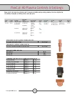
Page 12: ...pply 87 109 psi 6 7 5 bar 380 SCFH 180 SLPM FlexCut 80 Single Phase 208V 1 50 60 or 230V 1 50 60 FlexCut 80 125 Three Phase 208V 3 50 60 or 230V 3 50 60 or 460V 3 50 60 or 575V 3 50 60 Machine Ground Dedicated Earth Ground Supplied By Customer PRECISION GEAR RACK AND PINION DRIVE SYSTEM Stepper Motors 3 390 oz in Gear Box 3 5 1 Gear Engagement Fixed Traverse Speed Up to 500 ipm 2 years from Invoic...

Page 13: ...ier only Utilize the back of the machine to park the gantry while loading material A dedicated earth ground must be provided and should be installed in a manner to reduce trip hazard The power lead included is limited to 10 feet 4400 74 67 Load From This Side Operator Console Plasma Machine Under Table Power Supply Air Supply Provided by Other Earth Ground Provided by Other MAINTAIN WORK AREA Moti...

Page 14: ...the front of the machine Step2 The FlexCut plasma unit is shipped with a factory ground attached to the star ground In addition a work ground is attached to the star ground to connect to your material to be cut If the work piece is painted or dirty it may be necessary to expose the bare metal to make a good electrical connection Please Note Use 6 AWG stranded wire to connect the star ground on the...

Page 15: ...c trician should connect the input leads to the Torchmate 4400 4800 4510 The Torchmate 4400 4800 4510 CNC machine requires clean dry oil free compressed air or nitrogen A high pressure regulator MUST be used with a compressor or high pressure cylinder Supply pressure must be between 87 110 psi 6 7 6 bar with flow rated rates of at least 300 SCFH or 140 SLPM AIRSUPPLYPRESSURESHOULDNEVEREXCEED110PSI...

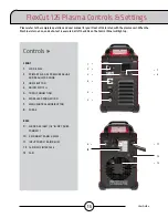
Page 16: ...p FRONT 1 CUTTING OPERATING MODE SELECTION 2 PRIMARY AIR GAS PRESSURE GAUGE AND REGULATOR KNOB 3 TORCH CONNECTION 4 SINGLE PHASE GREEN LED 5 POWER ON OFF GREEN LED 6 OUTPUT RED LED 7 THERMAL YELLOW LED 8 GAS PRESSURE YELLOW LED 9 PARTS IN PLACE PIP YELLOW LED 10 OUTPUT CURRENT KNOB 11 CNC INTERFACE 12 WORK GROUND BACK 13 INPUT CORD 10 ft 3 0 M 14 POWER SWITCH 15 AIR OR GAS INLET 1 4 in NPT QUICK C...

Page 17: ... 645 96 44 80A 140V 80 3PH 80 41 37 21 18 14 230 1 50 60 60A 140V 100 80A 140V 80 1PH 100 48 1PH 80 62 1PH 25 80A 200 208 1 50 60 60A 140V 100 80A 140V 60 1PH 100 52 1PH 60 71 25 80A MECHANIZED CUT CAPACITY MATERIAL THICKNESS MILD STEEL Recommended cut capacity at 24 ipm 3 4 in 19mm MAXIMUM CUT SPEEDS MILD STEEL 1 4 in 6 35 mm 148ipm 1 2 in 12 7 mm 52ipm 3 4 in 19 mm 26ipm PIERCE CAPACITY MATERIAL...

Page 18: ...cuted all of the LEDs on the Control Panel will light up FRONT 1 LCD DISPLAY 2 PRIMARY AIR GAS PRESSURE GAUGE AND REGULATOR KNOB 3 HOME BUTTON 4 ON OFF SWITCH 5 TORCH CONNECTION 6 WORK LEAD CONNECTION 7 MENU CONTROL KNOB BUTTON 8 PURGE BACK 9 AIR OR GAS INLET 1 4 IN NPT QUICK CONNECT 10 RECONNECT PANEL ACCESS 11 INPUT CORD STRAIN RELIEF 12 14 PIN CNC INTERFACE 13 FAN Controls 1 12 11 8 13 2 3 4 5 ...

Page 19: ...r 20 72 x 12 25 x 25 53 526 x 311 x 648 118 53 5 MECHANIZED CUT CAPACITY MATERIAL THICKNESS MILD STEEL Recommended cut capacity at 32ipm 1in 25 4mm MAXIMUM CUT SPEEDS MILD STEEL 1 4 in 6 35 mm 180ipm 1 2 in 12 7 mm 72ipm 3 4 in 19 mm 40ipm 1 in 25 4 mm 23ipm PIERCE CAPACITY MATERIAL THICKNESS MILD STEEL Pierce capacity with programmable torch height control 3 4 in 19mm CONSUMABLES STARTER KIT FOR ...

Page 20: ...he Accumove and start the computer If a grey WINDOWS screen appears swipe your finger up on the touchscreen monitor Enter cncop into the password prompt Press the arrow Press SHUTDOWN Once the computer boots up it will launch the Visual Machine Designer software A prompt will display Turn Off the Accumove Controller before pressing OK Press on the E STOP button to power down the controller On the ...

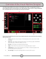
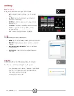
Page 21: ...rview of all the buttons and functions will be covered in sections 1 Job Group Opens and controls all aspects of the file being entered or the creation of jobs Includes SHUTDOWN 2 View Screen Shows the Process Setup graphic of the job g code of the job graph of the AVHC lifter station movements and Oxy Fuel and Water Fill controls 3 Run Group These buttons control the start and stop of the job 4 J...

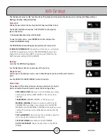
Page 22: ...e VMD Nesting program See the Nesting section for an overview of the features Shape Library Feature opens the dialog to create a user defined shape based on 36 of the most common parts See the USING THE SHAPE LIBRARY section for details Plate Setup The options in Plate Setup allows you to make alterations to the job itself and control the water level on water table configurations ROW AND COLUMN Al...

Page 23: ...ng down the system Prompts a dialog box to TURN OFF ACCUMOVE CONTROLLER Press the E Stop button to power down the controller The computer will then shut down Turn the power switch to OFF Process Stations Configure and control the tool outputs on the machine Kerf Add a Kerf value to compinsate for the tool kerf value Set Offset Capture the distance based on the torch position to a Plate Origin On O...

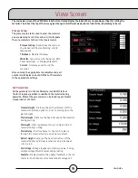
Page 24: ...er Cut Charts Transfer Height Distance the torch will retract off the material to initiate a pilot arc prior to moving up to the pierce height Pierce Height Distance the head sits above the material during piercing Cut Height Distance between the torch tip and top of material during cutting Pierce Delay The time delay for the torch to pierce through the material before executing movement Retract H...

Page 25: ...ation s movement during operation Maximize Viewport Displays all views in one screen Graphics View The machine limits are displayed in blue The head is represented with white crossed lines Plasma assigned tool paths are displayed in red Plate Marker assigned tool paths are displayed in green Rapid travels will be a dashed grey line Zoom to Machine Zoom to the programmed machine limits Zoom to Job ...

Page 26: ...ine along with running jobs Active Run Dry Run Toggles between ACTIVE RUN and DRY RUN ACTIVE RUN Activates your torch to fire when you RUN a job DRY RUN Deactivates your torch from operation If in DRY RUN the torch will simulate all movements without firing the torch Run Job Run Job Starts the job that is loaded into the VMD Stop Stops any activity or motion of the machine Reset The resets the job...

Page 27: ... body will move faster Continuous will move as long as your finger is active on the direction FEED RATE OVERRIDE Alter the running feedrate of the job that is active The feedrate updates the change on the next ARC ON command Incremental Jog Pressing a direction will travel the torch the assigned Incremental Distance Using the slider will give you increments between 000 100 Directly enter any numbe...

Page 28: ...ocess setup tab User Defined You can manually enter the cut parameters based off of the cut charts found in the FlexCut manual Sample Voltage is a toggle between On or Off On with MODE AUTO At the beginning of the cut the controller learns the proper Arc Voltage and maintains the desired Cut Height value entered in the CUT PARAMETERS Off with MODE AUTO The AVHC will adjust based on the set voltage...

Page 29: ...tion Dashboard The dashboard displays the host indicators and tools for the operator Arc Voltage Displays Arc Voltage feedback from the plasma during cutting Plasma Pierce Count This is used for keeping track of how many pierces the plasma consumables make You will RESET every time you change the consumables Process This displays the current cutting process Feedrate This displays the feedrate over...

Page 30: ...or running a program using dry run with the laser enabled How the Laser Works The laser is positioned at a slight angle to the torch so that it crosses directly under its centerline With the torch positioned properly on the machine and the material thickness entered into the system the z axis will make a position adjustment when activated so that the projected dot will land on the surface of the m...

Page 31: ...ected Configure Your Shape First you will select the tool you are planning to use Plasma Plate Marker or Oxy Lead In Radius Creates a radium for your lead in If a line lead in is required then enter 0 Lead In Length of the pierce point movement into the tool path This is usually 12 Lead Out Length of the cut created out of the cut path If using plasma enter 0 Overburn The measured length past the ...

Page 32: ... folder you will need to press browse and locate your job For the Is the job kerf compensated option The shape library parts do not accommodate for kerf compensation Select No and it will add the kerf based on the material thickness to the part On VMDNest and TMCAD programmed jobs select Yes Once selected press OK The job will display in the graphics screen UsingtheShapeLibrary ...

Page 33: ...l display Please switch the drives on Press hide and then in the lower left corner press Datum The torch will travel to the limits of the machine and establish the machine zero Open a Job Once machine zero has been established it is time to open a job and get it prepared to cut Press select job and locate your file Set your Process In the Process Setup tab enter in the material thickness and amper...

Page 34: ... toggle to Dry Run Press Run Job This will simulate the job loaded without firing the plasma torch If satisfied with the Dry Run and the machine movements toggle Dry Run to Active Run to cut the job loaded Press Run Job If you find that the machine is moving too fast for the material you can alter the feedrate by using the Feedrate Override slider bar By default the slider is set to 100 To slow do...

Page 35: ... higher or lower according to the thickness of the material and amperage you are running Load the LINE SPEED TEST gm file Enter in the AVHC settings according to the cut chart Jog the head to the bottom left corner SET PLATE ORIGIN Run the LINE SPEED TEST Once the test is complete there are a few things to look for On the top of the cut you want to see a clean cut without a lot of bevel Ideally it...

Page 36: ...31 User Guide Build Your Own Cut Chart Use this template to create your own custom cut charts using the line speed test Material Thickness Type Amperage Cut Speed Pierce Delay Pierce Height Cut Height ...

Page 37: ...or the size of material you enter in Start by clicking the Nesting button and it will display the Nested Job List screen To start a new nest press Nested Jobs Select New Nested Job and the Add Nested Job dialog opens In this dialog enter a name for your nest in NESTED JOB NAME This will become the file name of your project Each dialog after is a drop down Enter the thickness of material you plan o...

Page 38: ... at C ControllerData Jobs The two check boxes Verify and Artwork Verify will display the parts to look at layers and other details on the individual parts Artwork will change the toolpaths to an ONLINE toolpath and bypass the kerf adjustments On the right is the Job Properties that will be applied to your parts when posting Importing Properties holds basic changes to the POST and importing of the ...

Page 39: ...ust a single part then in the right toolbar select Complete Nest This will open the Create Job Dialog Enter the location you want the job to save to and verify the amperage you are cutting Then press OK OpenNestinVMD In the Nest screen at the bottom left press the Back Run button and it will return you to the VMD Run screen To run your nest go to Select Job and locate your file In the AVHC tab tog...

Page 40: ...sh the machine 4 In the PROCESS SETUP tab enter the material thickness 3 16 188 along with the amperage on the plasma cutter FC80 40amp FC125 65amp This will populate the CUT PARAMETERS to the proper set tings based off of the cut charts 5 Press SELECT JOB 6 Locate the 4x00 80 125 R6 gm Since this file is tool pathed IS KERF COMPENSATED Select YES and press OK There are four files loaded to the ma...

Page 41: ...ssive wear Theshieldcap hold it up to a light and check if any of the holes are plugged If they are then replace the shield These holes are the outlet for the shield gas and when clogged they can misshape the plasma arc which leads to imprecise cuts Theretainingcap is the most durable of the consumables and will only need to be replaced when corrosion clogging or cracking is physically apparent Th...

Page 42: ... Mobil SHC Mobilith SHC 100 Lithium based grease This can be sourced and purchased locally Load the grease cassette into a grease gun and follow these steps to grease the side rails The back plate should now be exposed Take a rag to remove any metallic debris from the two magnets or the three detent positions To mount the torch align the top edges of the torch mount first slowly positioning the to...

Page 43: ...covers removed the zerk fittings will be visible Attach the grease gun and pump until the grease comes out from the pocket where the bolt and spring enter the assembly AsNeededMaintenance The following is based on how often the machine is being used If the machine is running once a week the following steps will not be needed as often as a machine running every day Bellows The bellows are a consuma...

Page 44: ... on usage There is a plumbing valve 1 2 inch located in the back left corner of the table To dispose of water please contact your local EPA or water district authorities After the water has been drained remove all pieces of metal and discard according to local and federal regulation Close the valve and refill the table with water The 4400 holds 60 gallons 230 liters the 4800 holds 107 gallons 405 ...

Page 45: ...and the best bevel is achieved by using a climbing cut The best bevel is to the right of the direction of travel Corners can have more bevel than a normal cut This is caused when the machine slows down for the direction change A lower amperage in some cases allows for slower travel speeds and reduces slowdown bevel through corners Sharp corners can be achieved by cutting a larger shape that puts t...

Page 46: ...h height Torch too low Equal bevel on all sides Minimal bevel Longest consumable life Unequal bevel One side may be straight the another excessively beveled Can be caused by worn tip Excessive bevel Cut may not go all the way through material Reversed bevel Torch may contact material and short out or damage tip Position of torch while cutting Bevel of finished part ...

Page 47: ... mode on contacting the material causing the cut to not fully penetrate the material When the machine begins to move before a pierce is completed the cut will not complete In this case the dwell time or pierce delay must be adjusted to allow for enough time to pierce the material When a cut s path does not return to the starting point there may be mechanical slipping or binding In some cases it wi...

Page 48: ... quality Check consumables in the Plasma torch along with the settings from the cut chart Check the torch is square to the material on the table Follow the CUT QUALITY section pg 29 Problem Solution An error message occurs when attempting to turn the Laser on stating The laser cannot be activated in Active Run Toggle the system to Dry Run mode The laser does not appear to be landing where the cent...

Page 49: ...terial entered in Error IHS Failure Check VFC Ground Check to make sure the Orange Ohmic Wire is con nected to the ohmic clip Validate the clip is contact ing the shield Check that the material surface is free of rust or corrosion that may inhibit an electrical contact with the shield See Ohmic Troubleshooting Guide Error IHS Failure Clear slag from consumables With the torch not contacting the ma...

Page 50: ...art out but does not fire Check that the Dry Run Active Run button says Active Run If OK to Move is disabled check Plasma Power Supply for errors Verify that the g code has M64 M65 in the code If not then the POST isn t configured correctly in the TMCAD The torch stays firing between cuts and the job preview shows solid red lines for all of the machine s motions When in the Torchmate CAD CAM softw...

Page 51: ...ully on the back of the controller Accumove 3 The torch does not retract off the material when moving between cuts but the torch does shut off Jog the Z axis all the way to the top of its travel and click Reset Z then click Run Job Verify that the Retract Height value is set to the desired retract distance in between cuts Part way through a program a Limit Exceeded in X or Y axis occurs When execu...

Page 52: ...ler when the switch is turned ON The controller won t turn on Accumove 3 Disengage the E STOP Verify the power cable is plugged in Verify the fuse on the back power port is in intact Verify the Voltage Selector switch is set to the proper 110v or 220v incoming power The controller has a Blinking Power light Accumove 2 An input is shorted to ground disconnect the Breakaway Height Control and Input ...

Page 53: ...on Return to Select Job and reopen the job If the part displays incorrectly the issue is pres ent in the g code file itself and it must be recreated correctly Error occurs Execution Error Overtravel Detected when clicking the Run Job button Verify that all home and limit switches are not depressed TMX table Only If operating near the extents of the machine re set program zero and material further ...

Page 54: ...s cutting too high from the material Verify Pierce and Cut height are at recommended book values Verify the height control mode is set to Auto and not Manual Verify the Sample Voltage function is turned ON Check for part tip ups near the piercing points that may interfere with the torch sensing the materials height Torch does not appear to maintain a consistent cut height with the material as it w...

Page 55: ......

Page 56: ...ion Accordingly Lincoln Electric does not warrant or guarantee or assume any liability with respect to such information or communications Moreover the provision of such information or technical information does not create expand or alter any warranty on our products Any express or implied warranty that might arise from the information or technical information including any implied warranty of merc...

Reviews: