background image

Suzhou  Lily  Tech.  Co.,  Ltd. 


Page  1, Total  8  Pages


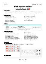
ZL-6x0A Temperature Controller 

Instruction Manual,  V4.

6b


1.


Introduction 

ZL-6x0A series thermostat are suitable for control of cold storage, seafood storage, water heater, and 

so on. 


2.


Main Function 

Cooling or heating mode   

Periodic or intellectual defrost     

Fan control   

Temperature calibration   

High/low over temp. warning 

Temp. output delay protection   

Sensors failure warning   

Buzzer warning 

External warning input   

 
3.


Models 


4.


Main Specification  

Sensor wire: 2 meters 

Sensor: NTC

(R

25

=5K, B

25/50

=3470K)


Setting range: -40~120


Display range: -50~130


Power supply: 185~245Vac, 50/60Hz 
Terminal wire: ≤ 2*1.5mm

P

2

, or 1*2.5mm

P

2


Load: 3A, 10A, 250Vac (resistance) 

Storage: -30~70


Working: -10~45


Working: 5~85%RH without dew   

Case materials: PC + ABS fire proof 

Protection level: IP65 (Front side only) 

Dimension: L78 x W34.5 x D71 (mm) 

Installation drilling: L71 x W29 (mm) 


5.


Operation 

5.1 Power-On Display 

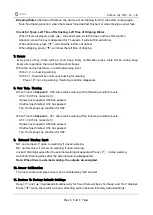
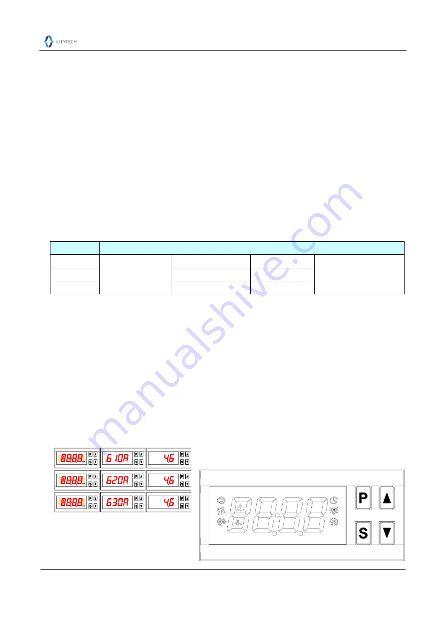
After power on, all LED unit will be on, then model name, and firmware version:


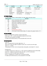
5.2 Display Icon 

4. Model 

Function 

ZL-610A 

Cooling/heating


Periodic defrost 


External warning input 

ZL-620A 

Intellectual defrost 


ZL-630A 

Intellectual defrost 

Fan control 

Summary of Contents for ZL-6 0A Series

Page 1: ...ication Sensor wire 2 meters Sensor NTC R25 5K B25 50 3470K Setting range 40 120 Display range 50 130 Power supply 185 245Vac 50 60Hz Terminal wire 2 1 5mmP 2 or 1 2 5mmP 2 Load 3A 10A 250Vac resistance Storage 30 70 Working 10 45 Working 5 85 RH without dew Case materials PC ABS fire proof Protection level IP65 Front side only Dimension L78 x W34 5 x D71 mm Installation drilling L71 x W29 mm 5 Op...

Page 2: ...fault settings For example the password will be 1111 5 4 Set Set Point Keep S depressed for 3 seconds to enter into the status Press or to set the value keeping depressed can fast set Press S to exit and save the settings The status will exit without saving if no key operation within 30 seconds 5 5 Set Parameters Password Keep P depressed for 3 seconds digits show 0 Press to select the digit of th...

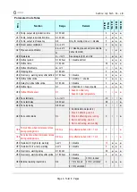
Page 3: ...efrost after online 0 180 min 0 disable 0 U38 Defrost type 0 1 0 Electrical 1 Gas or pump 0 U39 Defrost finish sensor 0 1 0 based on timer only 1 based on pipe temperature 1 U40 Fan start temp 45 120 10 U41 Fan start delay 0 600 sec 60 U42 Fan stop delay 0 600 sec 0 U43 Fan control mode 0 4 0 Controlled mode see 6 4 1 Stop in defrosting see 6 4 2 Stop in defrosting else running 3 Run in defrosting...

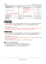
Page 4: ..._output forced energized When not defrosting keep depressed for 5 seconds can force Temp _output energized for 30 min During forced cooling keep depressed for 5 seconds will stop forced cooling 6 2 Heating Control If Troom Set point U22 and Temp _output has stopped for U10 then Temp _output energized If Troom Set point and Temp _output has run for U11 then Temp _output de energized Temp _output fo...

Page 5: ...ing U43 4 Fan runs during defrosting At other time fan keeps running also 6 5 Protecting Run When Room Sensor Fails for Cooling Mode When room sensor fails Temp _output will be energized and de energized periodically For every 30 minutes Temp _output will be energized for Trun U12 3 minutes de energized for 30 Trun minutes If U12 0 no protecting run 6 6 Run When Pipe Sensor Fails When pipe sensor ...

Page 6: ...ion disappears 8 Over Temp Warning When Troom Set point U50 there will be warning if the following condition meets U50 0 U50 is not set to 0 If power just supplied U53 has passed If defrost just finished U34 has passed The Troom keeps up condition for U52 When Troom Set point U51 there will be warning if the following condition meets U51 0 U50 is not set to 0 If power just supplied U53 has passed ...

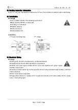
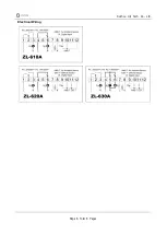
Page 7: ...ive air Installation 1st Insert into drilling hole 2nd Clamp 14 Electrical Wiring Warning Wiring work should be manipulated by certified technicians Supplied power should within specification requirement Sensor and input signal bundles should not be laid together with power supply bundles in same pipe Sensor s bundle is better as short as possible Not wind the redundant length bundle to electrical...

Page 8: ...Suzhou Lily Tech Co Ltd Page 8 Total 8 Pages Electrical Wiring ...

Reviews: