

10
28
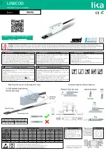
LINECOD
Absolute linear encoders
Series
SMA2
Complete documentation available for
download at www.lika.biz
Warning
: sensors having order code ending with "/Sxxx" may have mechanical and electrical characteristics different from standard and be supplied with additional documentation for special connections (Technical Info).
Attenzione
: i sensori con codice di ordinazione finale “/Sxxx” possono avere caratteristiche meccaniche ed elettriche diverse dallo standard ed essere provvisti di documentazione aggiuntiva per cablaggi speciali (Technical info).
Achtung
: Geräte, deren Bestellschlüssel mit der Kennung /Sxxx enden, können in ihren mech. und elektr. Eigenschaften vom Standard abweichen. Diese werden daher mit einer ergänzenden Dokumentation ausgeliefert (Technical info).
Atención
: los sensores con código de pedido acabado en "/Sxxx" pueden tener características mecánicas y eléctricas diferentes a las básicas y documentación adicional relativa a conexiones especiales (Technical Info).
Attention
: les capteurs avec code de commande terminant en “/Sxxx” peuvent avoir des caractéristiques mécaniques et électriques différentes du standard et documentation additionnelle pour les câblages spéciaux (Technical info).
EN
Mounting instructions
IT
Istruzioni di montaggio
DE
Montagehinweise
•
Fix the sensor by means of
two M3 20 mm min. long cylinder head
screws
; please check the sensor – scale mounting direction shown in Figure;
•
always comply with the mounting tolerances indicated in the Figure;
•
use the MTA2 type magnetic scale (refer to specific technical instructions);
the arrow indicates the standard counting direction (count up information);
•
recommended
minimum bend radius
of the cable:
R
≥
42 mm
;
•
after installing the sensor on the scale as well as after replacing the sensor
and/or the scale a zero setting operation is compulsorily required.
•
Fissare il sensore utilizzando
due viti M3 a testa cilindrica di lunghezza
minima di 20 mm
; rispettare l'orientamento tra sensore e banda e le
tolleranze di montaggio indicate in figura;
•
utilizzare la banda magnetica MTA2 (riferirsi alle specifiche istruzioni); la
freccia indica la direzione di conteggio positiva (conteggio crescente);
•
raggio di curvatura minimo
del cavo raccomandato:
R
≥
42 mm
;
•
dopo l'installazione del sensore sulla banda come pure dopo la sostituzione del
sensore e/o della banda è necessario eseguire un azzeramento.
•
Sensor mit
zwei M3 x 20 Schrauben
befestigen und die Montagerichtung
zwischen Band und Sensor beachten;
•
angegebene Montagetoleranzen einhalten;
•
nur mit Magnetband MTA2 einsetzen (s. MTA2 Benutzeranleitung); positive
Zählrichtung, siehe Pfeil;
•
Mindestbiegeradius
vom Kabel ist
R
≥
42 mm
.
•
nach Montage von Band und Sensor
die Geberposition muss auf Null gesetzt
werden (
Nullstellung).
ES
Instrucciones de montaje
FR
Instructions de montage
•
Fijar el sensor mediante los
dos tornillos M3 de cabeza cilíndrica (longitud
min. 20 mm)
; montar el sensor y la banda respetando la dirección de
montaje indicada en la Figura;
•
asegurarse de que las tolerancias de montaje indicadas en la Figura sean
respetadas;
•
utilizar la banda magnética tipo MTA2 (consulte la información adicional); la
flecha indica el sentido de conteo positivo (conteo ascendente);
•
radio de curvatura mínimo
recomendado del cable:
R
≥
42 mm
;
•
después de instalar el sensor así después de remplazar el sensor y/o la banda
poner a cero la posición del sensor.
•
Fixer le capteur en utilisant
deux vis type M3 à tête cylindrique (longueur
min. 20 mm)
; respecter la direction et les tolérances de montage entre le
capteur et la bande magnétique indiquées dans la Figure ;
•
s'assurer que les valeurs de tolérance indiquées dans la Figure soient
respectées ;
•
utiliser la bande magnétique type MTA2 (voir la documentation annexée) ; la
flèche indique la direction de comptage positif (comptage augmentant) ;
•
rayon de courbure minimum
recommandé du câble:
R
42 mm
;
•
après l'installation du capteur aussi bien que après le replacement du capteur
et/ou de la bande on doit exécuter une opération de mise à zéro.
Mounting the sensor on the magnetic scale
Recommended mounting tolerances
Gap sensor / MTA2 magnetic scale (D)
without cover strip
with cover strip
0.1 – 0.6 mm
0.1 – 0.4 mm
Electrical connections
Cable specifications
Connector type
M12 8-pin
Signals
M12 8-pin
M8 cable
Cavo M8
Kabel M8
Cable M8
Câble M8
Model: LIKA HI-FLEX M8 type cable
Wires: 6 x 0.14 mm
2
+ 2 x 0.22 mm
2
Shield: Tinned copper braid
External diameter: Ø 5.3 mm ÷ 5.6 mm
Impedance: 6 x 148
/Km, 2 x 90
/Km
Min. bend radius: Ø x 7.5
male frontal side
0Vdc
1
Black
Nero
Schwarz
Negro
Noir
maschio lato contatti
+5Vdc ±5%
2
Red
Rosso
Rot
Rojo
Rouge
Aufsicht Stiftseite
Clock IN + / MA +
3
Yellow
Giallo
Gelb
Amarillo
Jaune
macho lado contactos
Clock IN - / MA -
4
Blue
Blu
Blau
Azul
Bleu
mâle côté contacts
Data OUT + / SLO +
5
Green
Verde
Grün
Verde
Vert
Data OUT - / SLO -
6
Orange
Arancione
Orange
Anaranjado
Orange
A
1
7
White
Bianco
Weiß
Blanco
Blanc
B
1
8
Grey
Grigio
Grau
Gris
Gris
Shield
Case
Shield
Calza
Schirm
Malla
Blindage
Installation has to be carried out with power supply disconnected.
L’installazione deve essere eseguita in assenza di tensione.
Der Anschluss darf nur bei ausgeschalteter Versorgungsspannung erfolgen.
La instalación sólo debe ser efectuada en ausencia total de tensión.
Le montage du dispositif doit être effectué en
absence totale de tension.
1 Incremental signals provided in specific
versions only, see the order code. NPN
o.c.,+5Vdc ±5%, I
out
= 40 mA max


