8. Lightware Device Controller
UBEX series – Matrix Application Mode – User's Manual
101
8. Lightware Device Controller
UBEX series – Matrix Application Mode – User's Manual
101
MA
TRIX APPLIC
A
TION MODE
Applied F-series endpoint firmware package: v1.4.1 | Applied R-series endpoint firmware package: v1.4.1 | Applied MMU firmware package: v1.2.1 | LDC software: v1.34.0b2
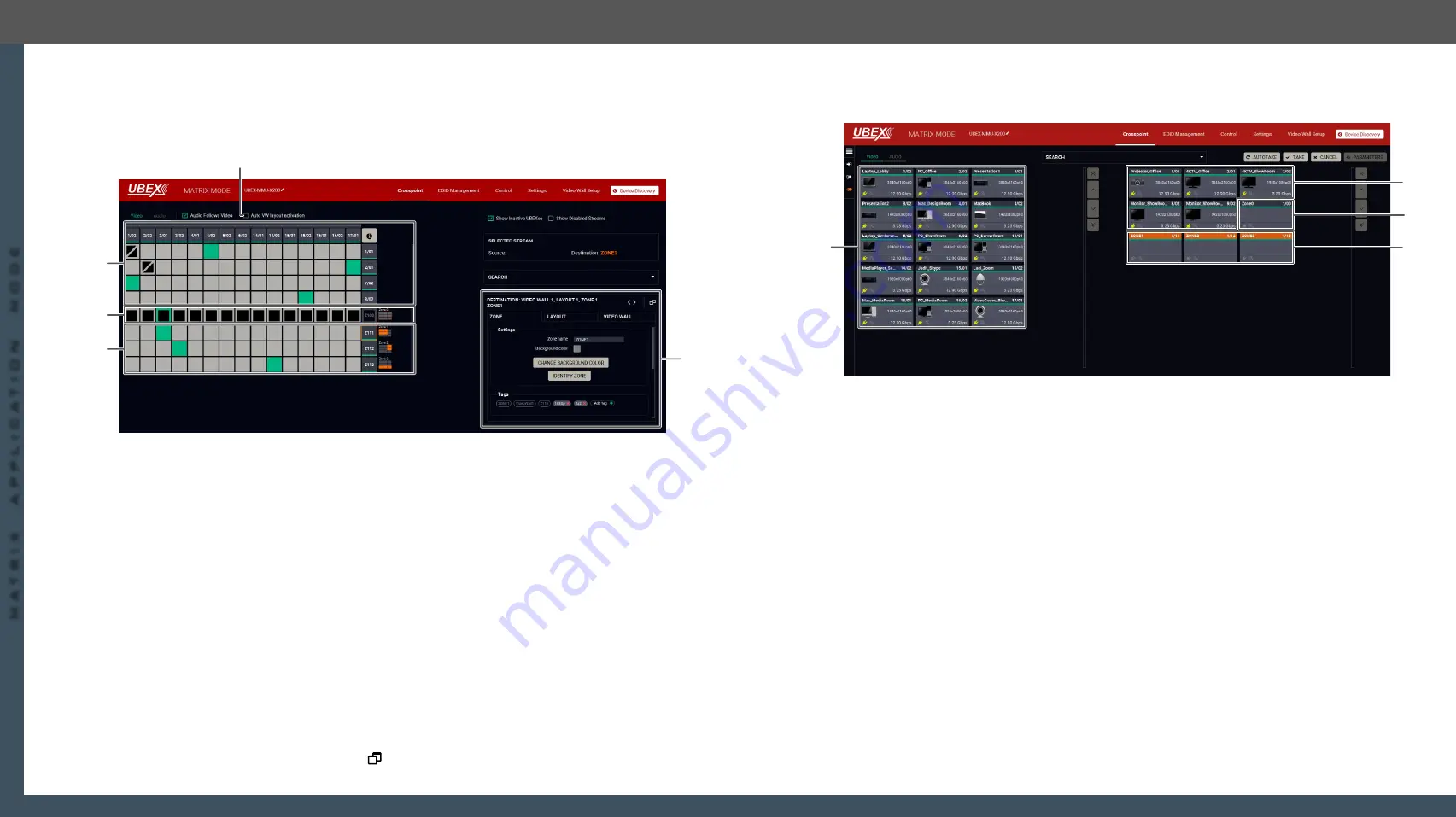
8.19.5. Crosspoint Menu with Video Wall
Grid View
Navigate to the
Crosspoint menu
-
Grid View
to select a source stream for the video wall.
Legend of the Crosspoint Menu
1
Auto VW layout
activation switcher
The explanation of the two available options are the following:
▪
Enabled
: the video wall layout becomes active suddenly when the
crosspoint setting is changed in it.
▪
Disabled
: switching of a source stream does not effect the video wall
layout activation.
2
Non-video wall
area
Source streams, destination streams, and the crosspoint connections which
are
not
the part of the video wall.
3
Video wall -
Layout0
Video wall area, Layout0 (the default layout of the video wall). Clicking on the
Zone tile ( on the Destination stream side) opens the
on the right side. The layout is not active currently.
4
Video wall -
Layout1
Video wall area, Layout1 (the layout which is created by the user). Clicking
on one of the Zone tiles (on the Destination stream side) opens the
on the right side. This layout is the active one.
5
Properties
window
The properties, available settings, and status information of the selected zone
are displayed in this section. Three tabs are available:
Zone
,
Layout
, and
Video
wall
. Clicking on the
icon the properties section opens in new window.
5
1
3
4
2
Tile View
Navigate to the
Crosspoint menu
-
Tile View
to select a source stream for the video wall.
Legend of the Crosspoint Menu
1
Source streams
Each tile represents a stream coming from one of the input ports of the
transmitter or transceiver. Each of them can be selected as a video source for
one of the video wall zones.
2
Destination
streams - non-
video wall area
Destination streams which are
not
the part of the video wall.
3
Video wall -
Layout0
Video wall area, Layout0 (the default layout of the video wall). Selecting the
Zone tile and clicking to the
Parameters
button opens the
. The layout is not active currently.
4
Video wall -
Layout1
Video wall area, Layout1 (the layout which is created by the user). Selecting
one of the Zone tiles and clicking to the
Parameters
button opens the
. This layout is the active one (highlighted with orange).
See the detailed information about the tile view of the crosspoint in the
#switch #crosspoint
3
2
4
1


