5. Software Control - Lightware Device Controller
RAP-B511 series
– User's Manual
30
Step 3.
Save the Schema by clicking
Save Configuration to Device
button. The configuration is saved to
Events
in the
(one event for one level settings). It can be seen in the event list, numbered
backwards.
INFO: Rotary LEDs give feedback about the current position of the jog dial knob. As it is rotated right (and
the volume increases), the LEDs turn on one-by-one. One level means half bright.
Volume Control Schema Table
Schema ID
Device Type
LWR-A
DP-TPS-TX220
DVI-HDCP-TPS-TX220
FP/WP-UMX-TPS-TX120, -TX130
HDMI-TPS-RX110AY
HDMI-TPS-TX220
MMX4x2-HDMI
MMX4x2-HT200
SW4-TPS-TX240
UMX-TPS-TX120, -TX130, -TX140
HDMI-3D-OPT-TX220
SW4-OPT-TX240
HDMI-3D-OPT-RX150RA
LWR-B
MX2-8X8-HDMI20-AUDIO, -L
MX2-16x16-HDMI20, -R, -Audio, -Audio-R
MX2-24x24-HDMI20, -R, -Audio, -Audio-R
LWR-C
MMX8x4-HT420M (mixer addon)
MMX8x4-HT400MC (mixer addon)
LWR-D
MMX6X2-HT200
MMX6X2-HT210
MMX6X2-HT220
LWR-E
MX-FR (IB/OB-A)
UMX-OPT-TX150R
UMX-TP-TX100
LWR-F
UBEX-PRO20-HDMI-F110, -F120
5.5.
Control Menu
5.5.1.
RS-232
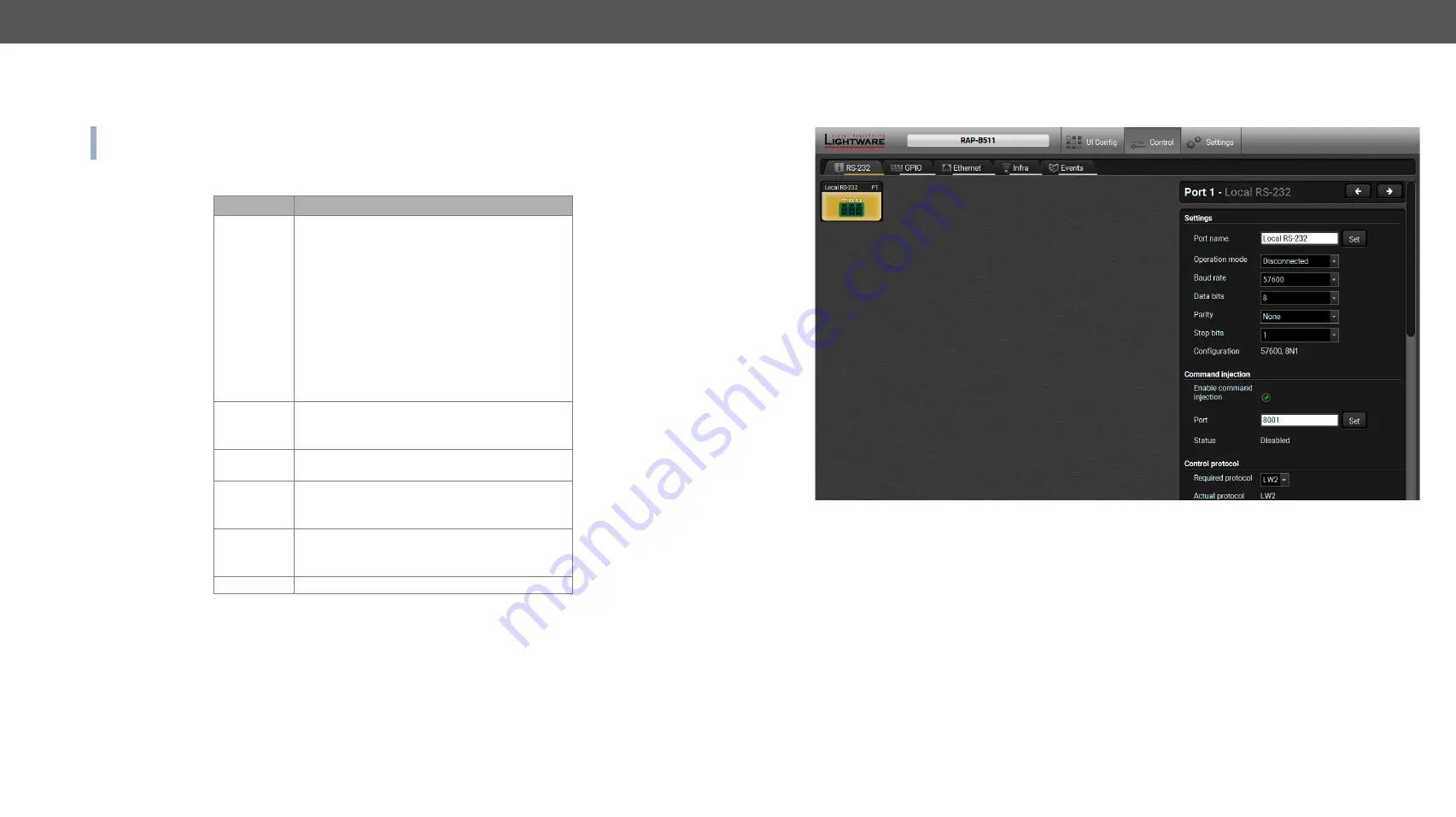
RS-232 Tab in Control Menu
The following settings and functions are available on the local RS-232 port:
▪
Port name
▪
Operation mode: Control, Command Injection, or Disconnected (for more details about serial interface
modes see the
section);
▪
Baud rate: 4800, 7200, 9600, 14400, 19200, 38400, 57600, 115200;
▪
Data bits: 8 or 9;
▪
Parity: None, Odd, or Even;
▪
Stop bits: 1, 1.5, or 2;
▪
Command injection: enable or disable;
▪
Command injection port number;
▪
Control protocol: LW2 or LW3;
▪
▪
Message sending via serial port;
▪
Reloading factory defaults (see factory default settings in the
section).


