4. Device Concept
RAP-B511 series
– User's Manual
21
4.4.
Outputs - Actions
Outputs of the Room Automation Panel can be a feedback about the executed event (e.g. after the button
press the button LED lights) or a control signal to the other device. Outputs can be set in the
(and in the
) in the
Software Control - Lightware Device Controller
(LDC) software.
4.4.1. Button LED Configuration
Button LEDs are customizable feedback of the user interaction or any input which is set as a condition. The
LED behavior takes into consideration of the status of the
interaction states
. For more details about it, see
section.The button LEDs can be configured separately.
LED states
Six different LED behaviors are available:
Off / Low brightness / High brightness / Blinking / Slow blinking /Sine pulse
Default LED function
The button LED can get a
default
function where two cases are defined:
▪
LED function for true state (when the
interaction state
is
true
)
Example:
Button1 is in Momentary operation mode, so when it is pressed, the interaction state changes true.
If the LED function for true state is on, the button LED will turn on while it is pressed.
▪
LED function for false state (when the
interaction state
is
false
)
Example:
Button2 Button3, Button4 are in the same radio group. When Button2 is pressed, its interaction
state changes true and the other's interaction states change false. If the LED function for false state is off
(by all buttons in the group), the LEDs of Button3 and Button4 will turn off.
Momentarily LED function
The Button LED can get a
momentarily
function. This overwrites the
default
function for a while. Duration
time has to be set if the LEDs
momentarily
function is off / low bright /high bright. Blinking number is
required when the LEDs
momentarily
function is blinking.
LED function settings has to be done with
Software Control - Lightware Device Controller
software (in
section) or with LW3 protocol commands (for more details see
section).
LED function
Off
Low bright
High bright
Blink
Slow blink
Sine pulse
Button
interaction state
True
False
Default function
Momentarily function
(ms or blinking
number)
LED function
validity
4.3.3.
IR Recognizer
The RAP-B511 has a built-in IR eye with IR recognizer function. The incoming signal is stored in hash
(fingerprint), and it can trigger actions in Event Manager.
INFO: All settings are available in the LDC software, more details can be found in the
section.
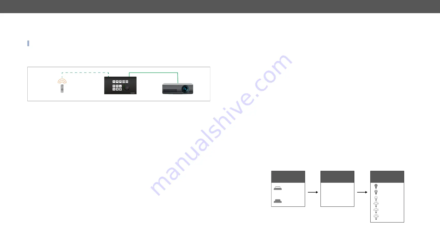
IR Recognizer Example
IR signals are sent by the Remote controller, the projector is connected to the Ethernet port of the RAP-B511.
The projector can be powered on via the RAP-B511 by using the remote controller with the following way:
▪
Set an action in Event Manager: if the power button is pressed on the Remote controller, the RAP-B511
sends a control command ('Power on') to the projector via Ethernet. In this case you can control the
device via the RAP-B511 remotely. See the details about the Event Manager settings in the
section.
4.3.4.
GPIO Input Level Change
The GPIO (General Purpose Input/Output) port is a multifunctional input/output interface to control the
RAP-B511 or third-party devices and peripherals. You can establish connection between the controller/
controllable device and the RAP-B511 by the 4-pole Phoenix connector. Three pin's direction is configurable
independently based on needs of the application.
When the GPIO pin is used as an input, it is able to receive feedbacks from the other device by changing the
input level. The configuration is available in
IR IN
Remote controller
Ethernet
ON
OFF
AUTO
RAP-B511
Projector


