background image


6. Software Control – Using Lightware Device Controller 

MX2-8x8-HDMI20 series – User's Manual 

22

6.3. 

Crosspoint Menu

6.3.1. 

Grid View

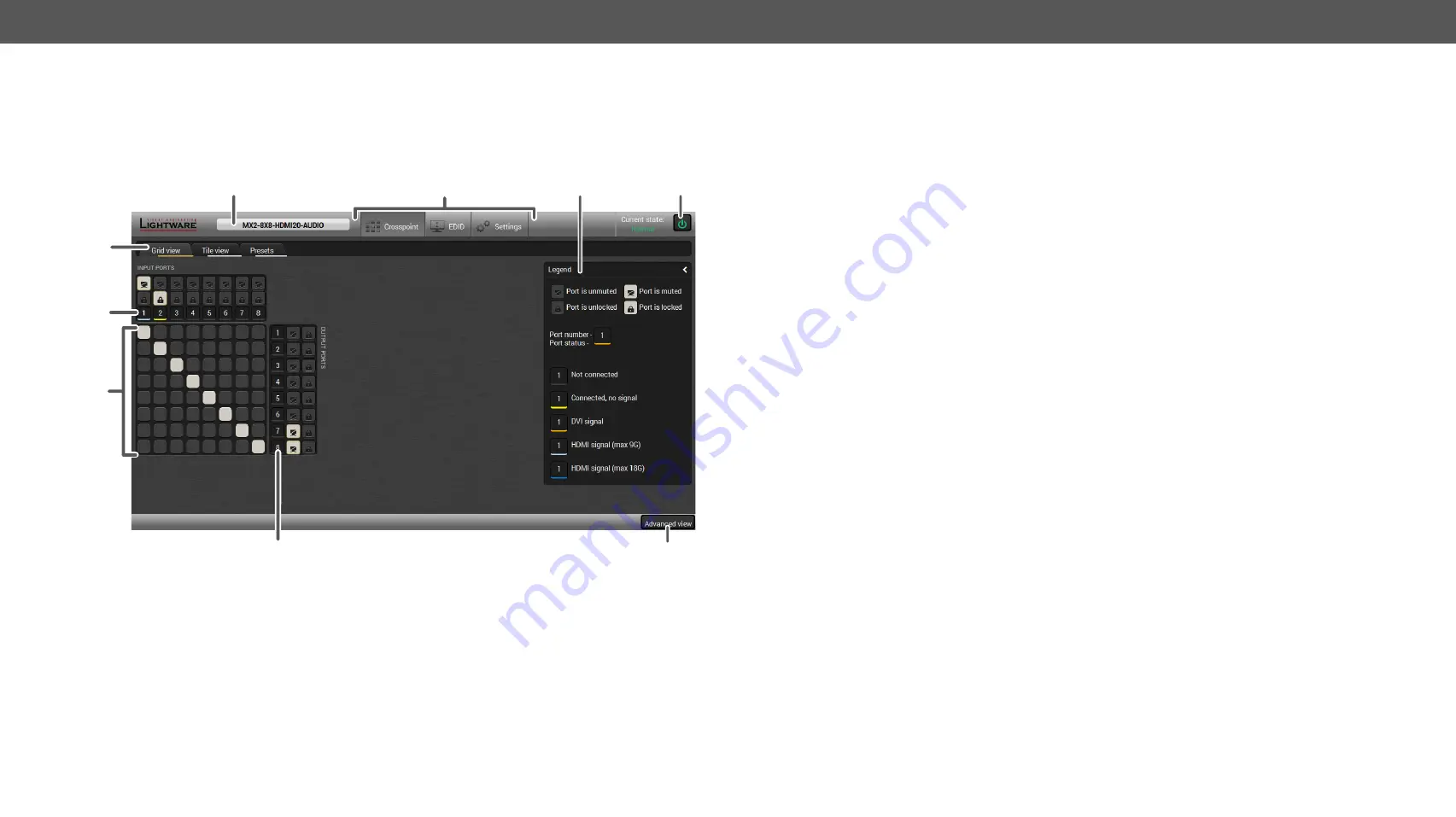
Grid view is a user-friendly graphical interface displaying the crosspoint state of the matrix router. This is an 

easy way to change between the input sources and output sinks.

2

5

1

4

3

9

8

7

6

1

Device Label

The 

Device Discovery 

window can be opened by clicking 

on this ribbon. The Device Label is displayed which is 

not the same as the Product Name. The Product name is 

displayed in a hint box when the mouse cursor is above 

the box. See more information in 

Status Tab 

section

,

 and 

Set the Device Label 

section.

2

Main Menu

The available menu items are displayed. The active one is 

highlighted with a dark grey background color

3

Legend Panel

The mute/lock icons and the applied colors of the input/

output ports are described in this panel.

4

Standby Switch

The device can be switched to 

Standby Mode

 or wake 

up  from  this  mode  by  the  button.  When  the  matrix  is  in 

standby mode the video transmission is disabled and the 

LCD is switched off. Remote connections (LAN, RS-232) 

remain enabled.

5

Tab Selector Ribbon

Select the desired 

Grid View, Tile View

, or 

Presets

 tab.

6

Input Ports

Each number represents an input port. Click on the port to 

display the 

Port Properties

 window.

7

Connections

Grey

  square  means  the  port  is  available  but  there  is  no 

connection. 

White

  square  means  there  is  a  connection 

between the input and the output port.

8

Output Ports

Each number represents an output port. Click on the port 

to display the 

Port Properties

 window.

9

Advanced View

Displaying the 

Advanced view 

page, showing the Terminal 

window and the LW3 protocol tree.

 

Summary of Contents for MX2-8X8-HDMI20-AUDIO

Page 1: ...MX2 8X8 HDMI20 AUDIO User s Manual Multimedia Matrix Switcher ...

Page 2: ...let the ventilation holes free and never block or bypass the ventilators if any WARNING To prevent injury the apparatus is recommended to securely attach to the floor wall or mount in accordance with the installation instructions The apparatus shall not be exposed to dripping or splashing and that no objects filled with liquids such as vases shall be placed on the apparatus No naked flame sources ...

Page 3: ...ature or a function TIPS AND TRICKS Ideas which you may have not known yet but can be useful Navigation Buttons Go back to the previous page If you clicked on a link peviously you can go back to the source page by the button Navigate to the Table Contents Step back one page Step forward to the next page Document Information This User s Manual applies to the following versions of the mentioned soft...

Page 4: ...6 6 3 EDID Summary Window 29 6 6 4 Editing an EDID 29 6 6 5 Creating an EDID 30 6 7 Settings Menu 30 6 7 1 Status Tab 30 6 7 2 Network Tab 31 6 7 3 RS 232 Tab 31 6 7 4 Front Panel Tab 31 6 7 5 System Tab 31 6 8 Advanced View 32 7 LW2 PROGRAMMERS REFERENCE 33 7 1 LW2 Protocol Description 33 7 2 Router Status Commands 33 7 2 1 View Product Type 33 7 2 2 View Serial Number 33 7 2 3 View the Installed...

Page 5: ...t 50 8 10 6 Unlock an Output 50 8 10 7 Conversion Mode 50 8 10 8 Scrambling 50 8 10 9 HDCP Setting Output Port 51 8 11 Audio Output Port Settings 51 8 11 1 Audio Mode Setting 51 8 11 2 Analog Audio Output Level Settings 51 8 12 RS 232 Port Settings 52 8 12 1 Protocol Setting 52 8 12 2 Baud Rate Setting 52 8 13 Network Settings 52 8 13 1 Query the Current IP Address 52 8 13 2 Set a Dynamic IP Addre...

Page 6: ...dded audio for amplifiers and audio systems Advanced EDID Management TheusercanemulateanyEDIDontheinputsindependently read out and store any attached monitor s EDID in 100 internal memory locations upload and download EDID files using Lightware Device Controller software Pixel Accurate Reclocking Each output has a clean jitter free signal eliminating signal instability and distortion caused by lon...

Page 7: ... 4K projector 4K monitor 4K 2K 60Hz 4 4 4 4K 2K 60Hz 4 4 4 Sn e in EU Hungary TX RX RS 232 LAN Sn SERV ICE Mad INPUTS HDM I 2 0 HDM I 2 0 HDM I 2 0 HDM I 2 0 HDM I 2 0 HDM I 2 0 HDM I 2 0 HDM I 2 0 OUT PUT S AUD IO AUD IO AUD IO AUD IO AUD IO AUD IO AUD IO AUD IO 2 3 4 5 6 7 8 1 2 3 4 5 6 7 8 1 Sn Ma de in EU Hu nga ry Ro HS Eth ern et 10 1 00 Bid irec tion al IR Bid irec tion al RS 232 HDM I 3D 4...

Page 8: ...in several ways by the supplied two rack ears Allen head screws fix them to the housing WARNING M4x8 size is the longest allowed screw for fixing the ears to the housing A longer screw may touch internal parts Mounting with Front and Rear Rack Ears ATTENTION Two rack ears are assembled on the matrix as default thus you will need two more rack ears for this kind of installation which can be purchas...

Page 9: ...to a LAN switch router and connect a controller e g a Touch panel Connect the power cord to the AC power socket and to the matrix 4K PC Media player 4K projector Audio amplifier Touch control Ethernet Power outlet Power HDMI HDMI HDMI LAN Audio 1 2 3 4 5 6 7 8 1 2 3 4 5 6 7 8 USB CTRL SOURCES DESTINATIONS MX2 8x8 HDMI20 Audio Compact HDMI 2 0 Matrix Switcher LIVE POWER IR RESET MAIN MENU System Se...

Page 10: ...the selected input port 4 Destinations Buttons to select an output or to view the state of an output 5 Function Buttons Switching between working modes Take Autotake and performing Preset operations 6 Status LEDs Blinking LIVE LED indicates normal operation POWER LED is dark in the case of an internal voltage problem 7 IR Detector Reserved for future developments 8 Reset Button Reboots the matrix ...

Page 11: ...r connecting sink devices Audio output ports 5 pole Phoenix with balanced analog audio output signal The signal is de embedded from the given HDMI port RS 232 Port The 3 pole Phoenix connector is used for the local RS 232 serial connection Compatible Plug Type Phoenix Combicon series 3 5mm pitch 3 pole type MC 1 5 3 ST 3 5 Ethernet LAN Port The matrix contains an RJ 45 connector for Ethernet LAN c...

Page 12: ...udio of the HDMI input signal or the Analog Audio signal coming from the 5 pole Phoenix input port The 5 pole Phoenix audio connectors next to the HDMI output ports can provide de embedded audio for amplifiers and audio systems HDMI Crosspoint 8x8 8x HDMI in Analog Audio in Embedder De embedder 8x HDMI out Analog Audio out Video Converter ...

Page 13: ...Audio This chapter is about the powering and operating of the device describing the functions which are available by the front rear controls Sample drawing shows that Input 1 is currently connected to the Output 2 3 and 5 ports If every source destination and Take buttons are unlit the unit is in Take mode and no input was selected in the last 3 seconds press and release a destination button to se...

Page 14: ...OL L L LO OC CK K L LO OC CK K O OU UT TP PU UT T 1 2 3 4 5 6 7 8 1 2 3 4 5 6 7 8 USB CTRL SOURCES DESTINATIONS MX2 8x8 HDMI20 Audio Compact HDMI 2 0 Matrix Switcher LIVE POWER IR RESET T TA AK KE E A AU UT TO O T TA AK KE E A AU UT TO O L LO OA AD D P PR RE ES SE ET T L LO OA AD D P PR RE ES SE ET T S SA AV VE E P PR RE ES SE ET T S SA AV VE E P PR RE ES SE ET T C CO ON NT TR RO OL L L LO OC CK K...

Page 15: ... 2 3 4 5 6 7 8 SOURCES DESTINATIONS MX2 8x8 HDMI20 Audio Compact HDMI 2 0 Matrix Switcher T TA AK KE E A AU UT TO O T TA AK KE E A AU UT TO O L LO OA AD D P PR RE ES SE ET T L LO OA AD D P PR RE ES SE ET T S SA AV VE E P PR RE ES SE ET T S SA AV VE E P PR RE ES SE ET T C CO ON NT TR RO OL L L LO OC CK K L LO OC CK K O OU UT TP PU UT T 1 2 3 4 5 6 7 8 1 2 3 4 5 6 7 8 USB CTRL SOURCES DESTINATIONS M...

Page 16: ...y the new settings RS 232 Submenu Adjustable parameters of the local RS 232 port Control enable disable the device control Baud Rate 9600 19200 38400 57600 115200 Protocol LW2 LW3 or P 2 protocol Time and Date The internal clock and date can be set in this submenu which is used for logging events Display Brightness The brightness of the LCD can be set from 1 to 10 on a scale ATTENTION The lowest v...

Page 17: ...compliant and turn off authentication if the content allows it Allow HDCP 1 4 only The connected source will detect that the sink is compliant with HDCP 1 4 but not compliant with HDCP 2 2 Allow HDCP 1 4 and 2 2 The connected source will detect that the sink is compliant with HDCP 2 2 factory default setting High Value mode Any version of HDCP is allowed on the input but the incoming signal is upc...

Page 18: ...version at frequencies above the threshold Forced on and Forced off settings override this operation TMDS Clock Rate However the clock rate can be set to 1 10 or 1 40 if necessary using the Auto setting is recommended Audio Submenu Information about the Analog and the Embedded Audio signal are displayed in this submenu Audio Present and Audio Type signal info Audio Mode Off HDMI Only Analog Only H...

Page 19: ... has multiple Ethernet connections for example Wi Fi and LAN connections are used simultaneously you will have to know the IP address for the one that is used for controlling the matrix Step 1 Connect the matrix and the computer either via Ethernet with LAN patch cable to a Hub Switch or Router or Ethernet with LAN cross cable directly to Computer Step 2 Change to the desired IP settings if it is ...

Page 20: ...llation for Mac OS X INFO After the installation the Windows and the Mac application has the same look and functionality This type of the installer is equal with the Normal install in the case of Windows and results an updateable version with the same attributes Mount the DMG file with double clicking on it and drag the LDC icon over the Applications icon to copy the program into the Applications ...

Page 21: ... button Further Tools The Tools menu contains the following options Log Viewer The tool can be used for reviewing log files which have been saved previously Create EDID This tool opens the Easy EDID Creator wizard which can be used for creating unique EDIDs in a few simple steps Functionality is the same as the Easy EDID Creator for the detailed information see Creating an EDID section Demo Mode T...

Page 22: ...rey background color 3 Legend Panel The mute lock icons and the applied colors of the input output ports are described in this panel 4 Standby Switch The device can be switched to Standby Mode or wake up from this mode by the button When the matrix is in standby mode the video transmission is disabled and the LCD is switched off Remote connections LAN RS 232 remain enabled 5 Tab Selector Ribbon Se...

Page 23: ... an input before preset loading it will also be locked to that input after preset loading so locked outputs ignore the preset 6 3 2 Tile View Thetilesrepresentinputoroutputportsandadditionallyshowthemostimportantportandsignalinformation Thus the user can check the status of many ports at the same time Control Buttons Mute or unmute selected output port s Open port properties window Lock or unlock ...

Page 24: ...ching mode Step 2 Select the desired port it will be highlighted with yellow color and displayed also on the port bar on the right Step 3 Connected ports are highlighted with white color and displayed also on the port bar on the right Step 4 Create the desired crosspoint settings by de selecting the ports the changes are executed immediately INFO Autotake mode remains active until it is switched o...

Page 25: ... switching to HDCP 2 2 sinks Any version of HDCP is allowed on the input but the incoming signal is always internally upconverted to HDCP 2 2 content and thus cannot be switched to HDCP 1 4 sinks Factory defaults Resetting the default values HDCP HDCP 2 2 or HDCP 1 4 Audio settings Audio source Off audio is not embedded in the video stream HDMI the audio of the incoming HDMI stream is embedded in ...

Page 26: ...n this case no signal is transmitted to the output port Lock The output port can be locked to the currently connected input port by the button If the port is locked button text is Unlock In this case the mute state cannot be changed Last attached display EDID The name of the last attached monitor s EDID is displayed shown as Monitor Name in the EDID menu HDCP capability Shows if the last attached ...

Page 27: ...DCP auto Signal type auto Conversion mode passthrough Scrambling auto TMDS clock rate auto Audio settings Mute analog output The analog audio output signal can be muted by this option Analog output volume Setting the value between 95 62 dB and 0 dB Analog output balance Setting the value between 100 and 100 0 center Factory defaults Resetting the default values Analog output unmuted Analog output ...

Page 28: ...n the Autotake button is highlighted with green the mode is active In this case confirmation is not required the selected preset is loaded immediately when the button is pressed Autotake mode Saving a Preset to an Empty Slot Step 1 Arrange the desired crosspoint connections in Tile view or Grid view Step 2 Select the Presets tab from the Crosspoint menu and type the desired Preset name in the indi...

Page 29: ...E1 E8 the currently emulated EDID for the input The source column displays the memory location that the current EDID was routed from The source reads the EDID from the Emulated EDID memory on the input port There are two types of emulation static and dynamic Static EDID emulation an EDID from the Factory or User EDID list is selected Thus the Emulated EDID remains the same until the user emulates ...

Page 30: ...s Manual EDID Editor Window Importing an EDID Previously saved EDID bin dat or edid file can be uploaded to the user memory Step 1 Select the User tab in the left panel and select a memory slot Step 2 Press the Import button below the Source panel Step 3 Browse the file in the opening window then press the Open button Browsed EDID is imported into the selected User memory ATTENTION The imported ED...

Page 31: ...y EDID Creator it is possible to create custom EDIDs in four simple steps By clicking on the Create button below the left panel Easy EDID Creator is opened in a new window Easy EDID Creator Wizard 6 6 Settings Menu 6 6 1 Status Tab General information about the product is displayed in this tab Device name read only Device label editable Part number and Serial number Hardware and firmware version n...

Page 32: ...settings are available on this tab RS 232 Tab in the Settings Menu 6 6 4 Front Panel Tab Certain settings in connection with the front panel LCD are available in the LDC as well LCD brightness the slider can be set to 0 contrary to the front panel menu When the value is 0 the LCD is totally dark Lock front panel the same as the Control lock button on the front panel Enable buzzer enable disable th...

Page 33: ...and starts with character received response starts with character The content of the window can be emptied by the Clear button If the Autoscroll option is ticked the list is scrolled automatically when a new line is added Place the mouse cursor on a line to display the date and time stamp in a Hint field 3 Protocol Tree LW3 protocol tree select an item to see its content 4 Edit Mode The default ap...

Page 34: ... Description Identification of the device Type i or I then the device responds its name 7 2 2 View Serial Number Description The device responds its 8 digit serial number Format Explanation in Input number in 1 or 2 digit ASCII format 01 5 07 16 etc out Output number in 1 or 2 digit ASCII format in2 Input number in 2 digit ASCII format 01 02 10 12 etc out Output number in 2 digit ASCII format 01 0...

Page 35: ..._DESC CrLf SL END CrLf SL 0 MX2 8X8 HDMI20 AUDIO V11_AAA0 CrLf SL END 7 2 7 View Crosspoint Size Description Shows the physical crosspoint size Explanation The matrix reports that it has an 8x8 crosspoint 7 2 8 View Router s Health Description Queries health status The response depends on the frame type Explanation Internal voltages temperature and fan speeds shown 7 2 9 Query Control Protocol RS ...

Page 36: ...ENTION The delay timeout applies for the receiving time of characters Please note that if LAN connection is used then the network may cause additional delays This could result that batch switching does not occur Below example shows a command that resulted batch switching The below example shows a command that does not resulted batch switching because another command has been inserted INFO The resp...

Page 37: ...cted to in Ox neither muted nor locked Ox M in Ox is connected to in Ox is muted and unlocked Ox L in Ox is connected to in Ox is not muted but locked Ox U in Ox is connected to in Ox is muted and locked Format Example Command VM vm Response MUT M1 M2 M3 M4 M5 M6 M7 M8 CrLf MUT 1 0 1 1 0 0 0 0 CrLf Format Example Command out 03 Response 1MT out CrLf 1MT03 CrLf INFO Muting does not change the cross...

Page 38: ...oller 7 2 5 FC View Installed Motherboard 7 2 6 IS View Crosspoint Size 7 2 7 GETSIZE View Router s Health 7 2 8 ST Query Control Protocol RS 232 7 2 9 P_ Operation See in section Command Switch an Input to an Output 7 3 1 in out Batch Switch Outputs 7 3 2 in out in out View the Connection of an Output Port 7 3 3 out View Connections of all Outputs 7 3 4 VC View Mutes on all Outputs 7 3 5 VM Mute ...

Page 39: ...ee structure is the node The node can have multiple child nodes but only one parent The tree has only one root the root node The leaves of the tree are also nodes which do not have child nodes The nodes are separated by a slash character All the slashes are right slashes no backslash is used The identifier of the root node is a slash The node name can contain the elements of the English alphabet a...

Page 40: ...Property value2 pw DeviceNickName John 8 1 1 3 Method The method in the LW3 protocol is also a leaf It cannot have a value such as the properties but it can be invoked with a parameter with the help of a special CALL command A method cannot have child nodes or child methods It is always a leaf A node can have any number of methods may not have any A method is referenced with a colon after the node...

Page 41: ...egal parameter count 006 Lw3ErrorCodes_IllegalOperation Illegal operation 007 Lw3ErrorCodes_AccessDenied Access denied 008 Lw3ErrorCodes_Timeout Timeout 009 Lw3ErrorCodes_CommandTooLong Command too long 010 Lw3ErrorCodes_InternalError Internal error 011 Lw3ErrorCodes_NotImplemented Not implemented 012 Lw3ErrorCodes_Node_Disabled Node disabled or standby mode active 8 1 4 Prefix Summary The followi...

Page 42: ...mmand Command format GET nodePath Response format n nodePath Example GET MEDIA n MEDIA SETTINGS n MEDIA XP n MEDIA NAMES n MEDIA PRESET n MEDIA SALVO n MEDIA PORTS Get all child nodes properties and methods of a node Get all child nodes properties and methods of a node with one command without using a wild card Command format GETALL nodePath Response format for nodes n nodePath Response format for...

Page 43: ...Access denied 8 3 3 Invocation A method can be invoked with the help of the CALL command Command format CALL nodePath methodName parameter Response format The response for a method execution is a state and a value The state is mandatory and always defined if the method could be executed It can be either a success or a failure The value is optional and it can contain additional information such as ...

Page 44: ...exadecimal value that can be optionally placed before every command In that case the response to that particular command will also be preceded by the signature and the corresponding lines will be between brackets Command format XXXX command Legend xxxx 4 digit long hexadecimal value Response format XXXX command lines Example 1103 GET MEDIA XP 1103 m MEDIA XP MultiLayer_Connect m MEDIA XP MultiLaye...

Page 45: ...ng the device through two independent connections Connection 1 and Connection 2 The events in the rows occur after each other Conn 1 OPEN MEDIA XP VIDEO o MEDIA XP VIDEO GET MEDIA XP VIDEO DestinationConnectionStatus pr MEDIA XP VIDEO DestinationConnectionStatus I1 I1 I1 I1 I1 I1 I1 I1 Conn 2 GET MEDIA XP VIDEO DestinationConnectionStatus pr MEDIA XP VIDEO DestinationConnectionStatus I1 I1 I1 I1 I...

Page 46: ...lNumber 87654321 8 5 4 Resetting the Matrix The matrix can be restarted the current connections LAN RS 232 will be terminated Command format CALL SYS softReset Response format mO SYS softReset Example CALL SYS softReset mO SYS softReset 8 5 5 Restore the Factory Default Settings Command format CALL SYS factoryDefaults Response format mO SYS factoryDefaults Example CALL SYS factoryDefaults mO SYS f...

Page 47: ... VIDEO switch OK Example CALL MEDIA XP VIDEO switch I4 O1 mO MEDIA XP VIDEO switch OK 8 6 3 Switching an Input to All Outputs Command format CALL MEDIA XP VIDEO switchAll In Response format mO MEDIA XP VIDEO switchAll OK Example CALL MEDIA XP VIDEO switch I1 mO MEDIA XP VIDEO switchAll OK TIPS AND TRICKS All output ports can be disconnected by the 0 value CALL MEDIA XP VIDEO switchAll 0 8 6 4 Mult...

Page 48: ...anation TEF T E F Unlocked Unmuted 1 1 1 0 1 1 1 1 Embeddedaudio presents Not encrypted Signal presents Connected Letter Character 1 Mute state Lock state T Unmuted Unlocked L Unmuted Locked M Muted Unlocked U Muted Locked Byte 1 Character 2 Character 3 BIT 7 6 BIT 5 4 BIT 3 2 BIT 1 0 Embedded audio status HDCP status Signal present status Connection status 0 0 Unknown 0 1 Reserved 1 0 No embedded...

Page 49: ...erscore _ and numbers 0 9 are accepted Example CALL MEDIA PRESET create My_pres VIDEO mO MEDIA PRESET create Explanation The preset is stored as a new node My_pres under the MEDIA PRESET node 8 8 2 Save the Settings to an Existing Preset Command format CALL MEDIA PRESET Pres_name save 1 Response format mO MEDIA PRESET My_Pres save Ok Example CALL MEDIA PRESET My_Pres save 1 mO MEDIA PRESET My_Pres...

Page 50: ... ANALOGAUDIO Gain 5 pw MEDIA PORTS VIDEO I1 ANALOGAUDIO Gain 5 8 10 Video Output Port Settings INFO The current setting can be queried by using the Get Command 8 10 1 Query the Status of the Output Ports Command format GET MEDIA XP VIDEO DestinationPortStatus Response format pr MEDIA XP VIDEO DestinationPortStatus I1_state I2_state I8_state The responses contain one letter and a 1 byte long HEX co...

Page 51: ... On SETTINGS Conversion OFF 420 LEFT RIGHT Legend Off no signal conversion 420 the signal is converted to the indicated color depth LEFT and RIGHT The device supports vertical splitting of an HDMI 2 0 4K 60Hz 4 4 4 input signal to left and right halves allowing for the transmission of an 18Gbps HDMI2 0 signal over two HDMI1 4 compliant links The two halves can then be recombined at the signal dest...

Page 52: ...xample SET MEDIA PORTS VIDEO O1 ANALOGAUDIO AudioMode HDMI pw MEDIA PORTS VIDEO O1 ANALOGAUDIO AudioMode HDMI 8 11 2 Analog Audio Output Level Settings Volume Setting the Exact Value Command format SET MEDIA PORTS VIDEO On ANALOGAUDIO VolumedB value Response format pw MEDIA PORTS VIDEO On ANALOGAUDIO VolumedB value Legend The Volume value can be set between 95 62 dB and 0 dB Example SET MEDIA PORT...

Page 53: ...xample SET MANAGEMENT SERIAL Baudrate 57600 pw MANAGEMENT SERIAL Baudrate 57600 8 13 Network Settings ATTENTION When any parameter of the network settings is modified always apply the new settings by using the following command CALL MANAGEMENT NETWORK applySettings INFO The current setting can be queried by using the 8 13 1 Query the Current IP Address Command format GET MANAGEMENT NETWORK IpAddre...

Page 54: ...tory EDID is emulated on the other input ports 8 14 2 Set the Emulated EDID Command format CALL EDID switch Source Destination Response format mO EDID switch Legend source Source EDID memory place F D U destination The emulated EDID memory of the desired input port E1 E8 More than one emulation can be set at the same time by using semicolons see Example2 Example1 CALL EDID switch U1 E4 mO EDID swi...

Page 55: ...4 Multiple Switching MEDIA XP VIDEO switchMulti O1_source O2_source O8_source Video Input Port Settings Operation Path 8 7 1 Query the Status of Source Port MEDIA XP VIDEO SourcePortStatus 8 7 2 Mute an Input Port MEDIA XP VIDEO muteSource In 8 7 3 Unmute an Input Port MEDIA XP VIDEO unmuteSource In 8 7 4 Lock an Input Port MEDIA XP VIDEO lockSource In 8 7 5 Unlock an Input Port MEDIA XP VIDEO unl...

Page 56: ... ON OFF 8 10 9 HDCP Setting Output Port MEDIA PORTS VIDEO On SETTINGS HdcpMode AUTO ALWAYS Audio Output Port Settings Operation Path 8 11 1 Audio Mode Setting MEDIA PORTS VIDEO On ANALOGAUDIO AudioMode 8 11 2 Analog Audio Output Level Settings MEDIA PORTS VIDEO On ANALOGAUDIO RS 232 Port Settings Operation Path 8 12 1 Protocol Setting MANAGEMENT SERIAL Protocol LW2 LW3 P 2 8 12 2 Baud Rate Setting...

Page 57: ...the LDU application Step 3 Establish the connection between the computer and the device s Step 4 Start the LDU and follow the instructions shown on the screen 9 3 Install and Upgrade Installation for Windows INFO The application can be installed under Windows XP or above Run the installer If the User Account Control displays a pop up message click Yes During the installation you will be prompted t...

Page 58: ...connected via an Ethernet cable and the connection is established between them 9 4 2 Start the LDU and Follow the Instructions After launching LDU welcome screen appears After pressing the A button a list will appear showing the supported devices Click on the Extender button on the main screen Step 1 Select the package Click on the Browse button and select the lfp file that will be used for the up...

Page 59: ...s in the device Three different status can exist Enabled by user all settings will set to factory default values Disabled by user your settings will be saved and restored after upgrading Enabled by default and not changeable by user firmware upgrade must perform a factory reset to apply all changes coming with the new firmware version Click on the Next button to continue Step 2 Select the device T...

Page 60: ...lick OK to continue Step 3 Upgrade the device A warning window will pop up before upgrading the device Do not unplug the power cable and the LAN cable while the upgrade is in progress Click OK to continue Click on the Start button to start the upgrade process After you confirmed the warnings and clicked on the Start button the upgrade process starts immediately ...

Page 61: ... red Restart the device and repeat the process Post Operation of the Upgrade in the Matrix After the part of LDU software upgrade process is finished the matrix starts the self upgrade procedure It is an automatic action and no any user interruption is needed during the operation The crosspoint buttons show the status of the process When all the 16 buttons light in green the upgrade is finished an...

Page 62: ...tion Refer to Video signal No picture on the video output Device s not powered properly Check the matrix and the other devices if they are properly powered try to unplug and reconnect them 3 3 Cable connection problem Cables must fit very well check all the connectors 3 3 No incoming signal No video signal is present on the HDMI input ports Check the source device and the HDMI cables 3 3 Not the p...

Page 63: ...port and set to HDMI or Auto 4 3 3 6 3 4 LW3 8 10 2 DVI EDID is emulated Check the EDID and select an HDMI EDID to emulate 4 3 4 6 6 LW3 8 14 Symptom Root cause Action Refer to RS 232 signal Connected serial device cannot be controlled Cable connection problem Check the connectors to fit well check the wiring of the plugs 3 3 Serial settings are different Check the port settings of the matrix and ...

Page 64: ...erent EDID on an input port of the Lightware device to have a different resolution but nothing happens Solution Some graphics cards and video sources read out the EDID only after power up and later they do not sense that EDID has been changed You need to restart your source to make it read out the EDID again 11 1 2 Advanced EDID Management Each DVI sink e g monitors projectors plasma displays etc ...

Page 65: ...able HDCP on the input port the transmitted signal will not be encrypted if the content is not protected Thus non HDCP compliant sinks will display non encrypted signal Not HDCP compliant Sink 2 Protected content Non HDCP compliant sink Encrypted signal MX2 8x8 HDMI20 series matrix HDMI cable HDMI cable 1 2 3 4 5 6 7 8 1 2 3 4 5 6 7 8 USB CTRL SOURCES DESTINATIONS MX2 8x8 HDMI20 Audio Compact HDMI...

Page 66: ...d screen HDCP v2 2 Stream type 0 the video stream allows to convert the signal to apply a lower level of encryption Stream type 1 the video stream does not allow to convert the signal 11 3 Pixel Accurate Reclocking Signal reclocking is an essential important procedure in digital signal transmission After passing the reclocking circuit the signal becomes stable jitter free and can be transmitted ov...

Page 67: ... Color LCD 320x240 pixels Rack mountable Yes 1U high rack ears supplied Material 1 mm steel Dimensions in mm 442 482 W x 43 7 H x 177 5 D Dimensions in inch 17 4 18 9 W x 1 72 H x 6 9 D Weight 3210 g with rack mounting ears RS 232 Control Port Serial port connector 3 pole Phoenix connector Available Baud rates 9600 19200 38400 57600 115200 Video Input Output Ports Port connector type 19 pole HDMI ...

Page 68: ...IO AUDIO AUDIO 2 3 4 5 6 7 8 1 SERVICE 15 5 14 7 15 2 116 442 482 14 1 177 5 43 7 29 3 Rear View Top View Side View Front View CONTROL LOCK LOCK OUTPUT SAVE PRESET SAVE PRESET LOAD PRESET LOAD PRESET TAKE AUTO TAKE AUTO USB CTRL SOURCES DESTINATIONS MX2 8x8 HDMI20 Audio Compact HDMI 2 0 Matrix Switcher LIVE POWER IR RESET Direction of the Airflow ATTENTION The ventilators are controlled automatica...

Page 69: ...40 24 99 Hz HDMI F130 3440 x 1440 29 99 Hz HDMI F131 4096 x 2160 25 00 Hz HDMI F132 4096 x 2160 30 00 Hz HDMI F133 4096 x 2160 60 00 Hz HDMI F134 3440 x 1440 23 99 Hz HDMI F135 4096 x 2160 24 00 Hz HDMI F136 3840 x 2400 29 99 Hz HDMI F137 3840 x 2160 60 00 Hz HDMI 2 0 F138 3840 x 2160 50 00 Hz HDMI 2 0 F139 Universal HDMI 2 0 EDID UHD PCM audio F140 Universal HDMI 2 0 EDID UHD all audio F141 4096 ...

Page 70: ...DCP mode Input port enabled v1 4 Output port Auto Color space color range Auto Auto Video conversion Off Scrambling Auto TMDS clock rate Auto HDMI mode Auto Emulated EDID F49 Universal HDMI all audio formats with deep color support on all inputs Presets saved by the User Erased Audio Input Output Ports Audio source Embedded audio Analog audio output Enabled de embedding from HDMI signal Analog Aud...

Page 71: ...merous types of regularly used connector and cable types to connect audio devices Please always make sure that a connector or cable fits your system before use ATTENTION Never join the phase inverted negative cold or poles either right and left to the ground or to each other on the output side as this can damage the unit INFO Use a galvanic isolation in case of a ground loop The Pinout of the 5 po...

Page 72: ...tware engineer unless expressly agreed beforehand 2 2 Used in any application other than that for which it was intended 2 3 Subjected to any mechanical or electrical abuse or accidental damage 2 4 Any costs incurred for repair replacement of goods that fall into the above categories 2 1 2 2 2 3 will be borne by the customer at a pre agreed figure 3 All products to be returned to Lightware require ...

Reviews: