6. Software Control – Lightware Device Controller Software
MX-FR Series Modular Matrix Frames – User's Manual
98
Applied CPU2 firmware: v3.5.7b8 | LDC software: v2.5.17b2
6.7.5.
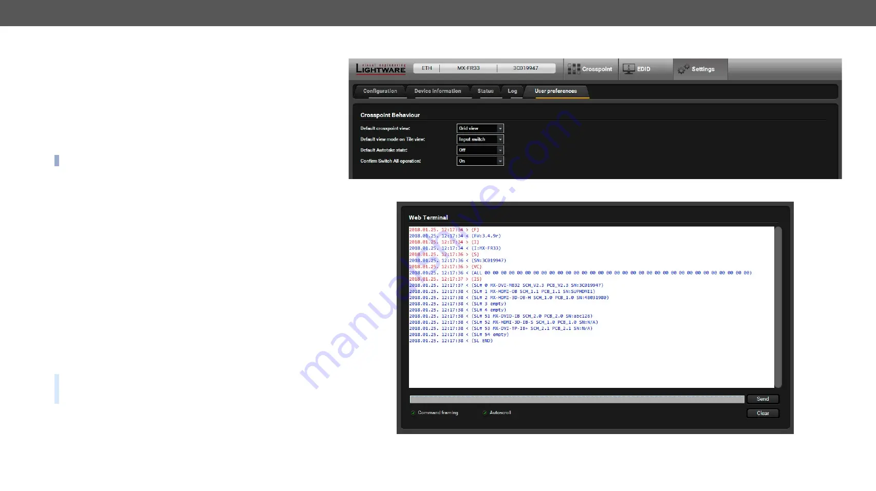
User Preferences
The tab shows some settings in connection with the LDC displaying/
working mode. These settings are saved by the LDC and applied next
time when the software is started (independently from the type of the
matrix):
▪
Default crosspoint view (Grid view / Tile view)
▪
Default view on Tile view (View mode / Input switch / Output
switch)
▪
Default Autotake state (On / Off)
▪
Confirm
Switch All
operation (On / Off)
INFO:
The size of the LDC window is also restored from the last run.
6.8.
Terminal Window
This general purpose terminal is intended mainly for testing and
debugging purposes. When a successful connection is established
with a router, this terminal can be used either via serial RS-232, TCP/
IP LAN or USB connection. All commands can be used here that are
discussed in the programmer’s reference. The command text can be
typed directly.
By default, commands are automatically surrounded by framing
brackets. Every sent command and every received response gets an
arrow (-> or <-) prefix, and has different font colors in order to help
distinguish between them.
The timecode in every row shows the exact time when the command
was sent or the response received.
If the
Command framing
checkbox is unchecked, you can send multiple
commands together, however in this case you have to type in the
framing brackets manually.
The terminal can be also opened after starting the LDC - press the
Terminal button on the Device discovery page on the bottom of the
window.
TIPS AND TRICKS:
The typed commands can be 'browsed' when
the cursor is in the command line and you press the up button on
the keyboard. The commands are stored until the LDC is closed.
#terminal
User Preferences Tab
Terminal Window


