AC PowerFor
Business-Critical Continuity™
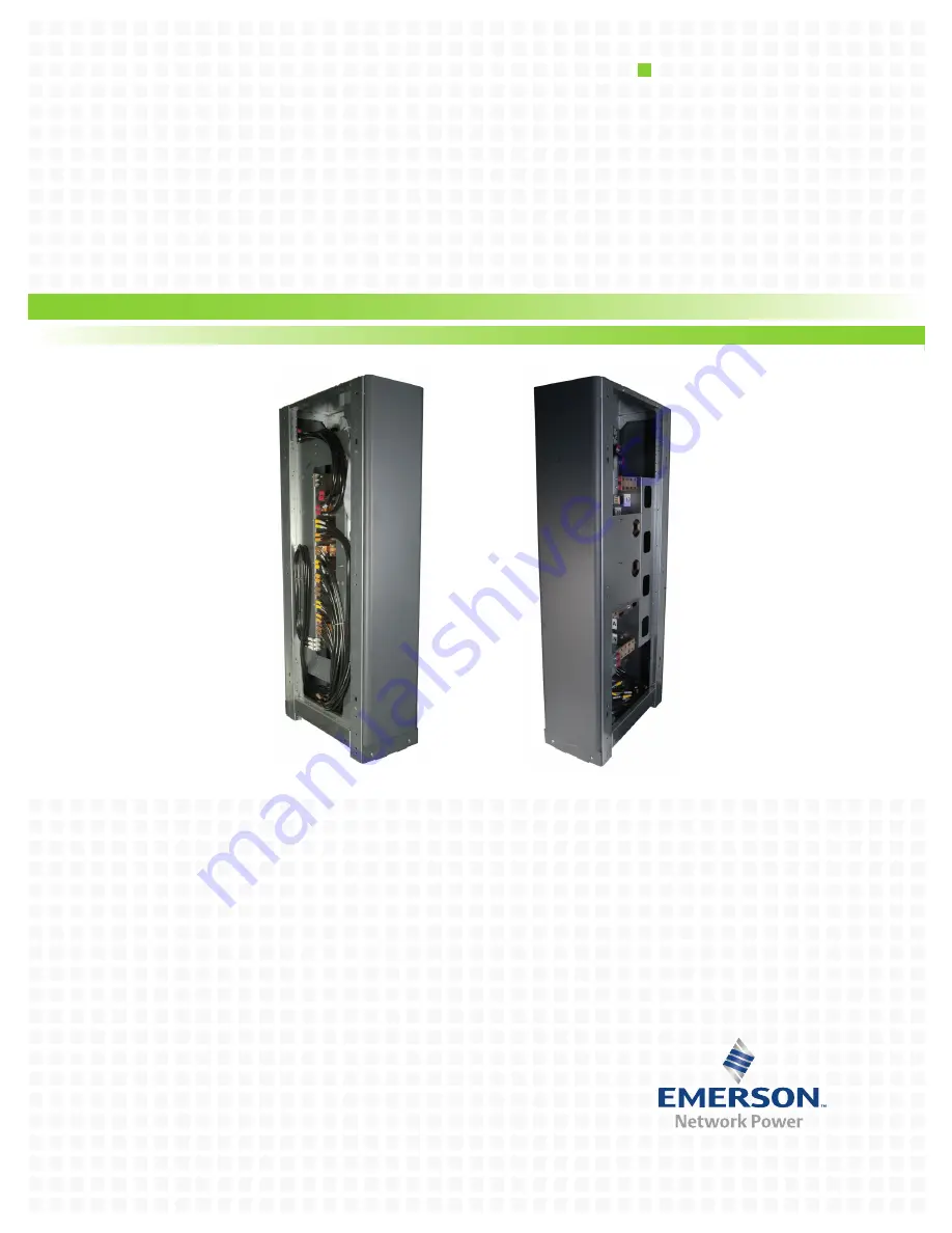
Liebert
®
NXL
™
Ship-Ahead Input/Output Cabinet
Installation Manual – 250-400kVA, 60Hz
Page 1: ...AC Power For Business Critical Continuity Liebert NXL Ship Ahead Input Output Cabinet Installation Manual 250 400kVA 60Hz...
Page 2: ...__________________________________________ Serial numbers ________________________________________________________________ Rating ______________________________________________________________________...
Page 3: ...0 300kVA Liebert NXL UPS 9 Figure 2 Input output conduit detail drawing 400kVA Liebert NXL UPS 10 Figure 3 Top cable entry routing and installation order 11 Figure 4 Bottom cable entry routing and ins...
Page 4: ...ii...
Page 5: ...f all maintenance procedures Observe all DC safety precautions before working on or near the DC system WARNING Risk of heavy unit falling over Improper handling can cause equipment damage injury or de...
Page 6: ...ally examine the cabinet for transit damage both internally and externally Report any dam age to the shipper immediately Verify that the correct equipment is being installed Verify that the UPS room s...
Page 7: ...e front of the equipment should be sufficient to enable free passage of personnel with the doors fully open Installation must leave a distance of 24 610mm between the top of the cabinet and any overhe...
Page 8: ...hich they are connected The cable design must comply with the voltages and currents in Tables 1 through 4 follow local wir ing practices and take into consideration the environmental conditions temper...
Page 9: ...cured connect the power cables as described in the fol lowing procedure Refer to the appropriate cable connection drawing in Figure 3 or 4 1 Verify that the equipment is isolated from its external pow...
Page 10: ...to accept power on the arrival of the commissioning engineer ensure that the system output cables are safely isolated at their termination WARNING Risk of electrical shock Can cause injury or death W...
Page 11: ...m Cable Entry Input Wire Conduit Ph N G THW RNC kVA kW Input Bypass Output 250 225 480 480 480 3 2 5C 3 2 0AWG 2 1 0AWG 1 0AWG 3 3C 3 2 0AWG 2 1 0AWG 1 0AWG 2 3C 3 250kcmil 2 4 0AWG 1 0AWG 2 3C 3 250k...
Page 12: ...5 733 2 3 AWG 54942BE 54811BE 1 AWG 54947BE 54857BE 1 0 AWG 54950BE 256 30695 593 2 0 AWG 54951BE 54862BE 3 0 AWG 54965BE 54864BE 4 0 AWG 54970BE 54866BE 250kcmil 54913BE 54868BE 300kcmil 54914BE 5487...
Page 13: ...ALUMINUM CABLES ARE NOT RECOMMENDED 9 ALL WIRING IS TO BE IN ACCORDANCE WITH NATIONAL AND LOCAL ELECTRICAL CODES LOW VOLTAGE 14 1 CONDUI T LOW VOLTAGE 1 5 CONDUIT LOW VOLTAGE 1 5 CONDUIT INPUT 2 3 CON...
Page 14: ...L ELECTRICAL CODES BYPASS NEUTRAL OUTPUT NEUTRAL INNERPANEL REMOVED FOR CLARITY GROUND BUS BOTTOM ENTRY 88 X 56 SLO T 6 PLACES EACH BAR LOW VOLTAGE 1 5 CONDUIT DC 2 3 CONDUIT BYPASS 2 3 5 CONDUI T INP...
Page 15: ...YPASS INPUT RECTIFIER INPU T OUTPUT OUTPUT NEUTRAL GROUND BOTTOM ENTRY FRONT VIEW DC CONDUIT Recommended order of installation for cables 1 DC Power 2 Bypass Neutral 3 Bypass Input Power Phases A B C...
Page 16: ...ation for cables 1 Output Neutral 2 Output Power Phases A B C 3 Rectifier Input Power Phases A B C 4 Bypass Input Power Phases A B C 5 Bypass Neutral 6 DC Power 7 Ground OUTPUT PHASE C RECTIFIER INPU...
Page 17: ...through removable access plates Remove punch to suit conduit size and replace 5 Unit bottom is structurally adequate for forklift handling 6 Control wiring and power wiring must be run in separate co...
Page 18: ...Installation Drawings 14...
Page 19: ......
Page 20: ...ration All names referred to are trademarks or registered trademarks of their respective owners Technical Support Service Web Site www liebert com Monitoring 800 222 5877 monitoring emersonnetworkpowe...