-115-
v5.8
Interacting with Waspmote Plug & Sense!
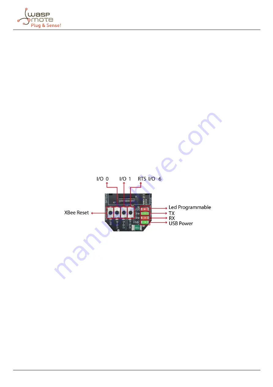
LEDs
Four indicator LEDs are included in the Gateway:
-
USB power LED: indicates that the board is powered through the USB port
-
X LED: indicates that the board is receiving data from the USB port.
-
TX LED: Indicates that the board is sending data to the USB port
-
I/O 5 configurable LED: associate
The configurable LED connected to the XBee’s I/O 5 pin can be configured either as the XBee’s digital output or as the XBee’s
indicator of association to the sensor network.
Buttons
-
Reset: allows the XBee module to be reset.
-
I/O - 0: button connected to the XBee’s I/O pin 0.
-
I/O -1: button connected to the XBee’s I/O pin 1.
-
RTS - I/O – 6: button connected to the XBee’s I/O pin 6.
All the buttons connect each one of its corresponding data lines with GND with when pressed. None of these have pull-up
resistance so it may be necessary to activate any of the XBee’s internal pull-up resistances depending on the required use.
Figure : LEDs in Waspmote Gateway
25.1.2. Linux receiver
When using Linux it is possible to use various applications to capture the input from the serial port. Libelium recommends to
use the ‘Cutecom’ application.
Once the application is launched the speed and the USB where Waspmote has been connected must be configured.
The speed that must be selected is 115200 which is the standard speed set up for Waspmote.
The USB where Waspmote has been connected must be added the first time this application is run, adding USB0, USB1, etc (up
to the USB number of each computer) according to where Waspmote has been connected. For this, the ‘Device’ window must
be modified so that if Waspmote is connected to USB0, this window contains ‘/dev/ttyUSB0’.
Once these parameters are configured, capture is started by pressing the ‘Open Device’ button.


