


16
COMMUNICATION KIT INSTALLATION
E
N
G
L
IS
H
1
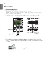
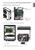
For connection to outdoor unit and to controller (Field supply) :
Pull the wires inside through the cable gland and close the nut firmly in order to ensure a
good pull relieve and water protection.
2
The wires require an additional pull-relief. Strap the wire with the support tie wrap.
3
For the wired remote controller wire and outdoor unit communication wire, remove the
coating at the end of the wire to connect and use the ring type (Ø3) to connect to the termi-
nal block.
Support
tie wrap
Nut of cable
gland
(Side view)
(Front View)
Cable Insert
Detail
Ring type (Ø3)
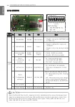
Connection of the wires
Electrical Work


