background image

MODEL

:

LPC-M155X , LPC12W

SE
R

VICE MANU

AL

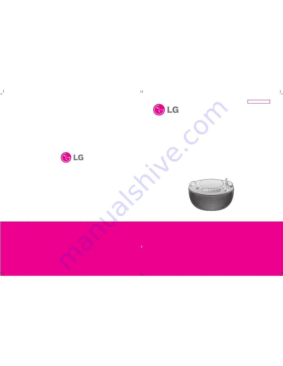
PORTABLE CD CASSETTE
RECORDER

SERVICE MANUAL

CAUTION

BEFORE SERVICING THE UNIT, READ THE “SAFETY PRECAUTIONS” IN THIS MANUAL.

MODEL :

LPC-M155X , LPC12W

Website http://biz.lgservice.com

Internal Use Only

P/NO : AFN62795896

NOVEMBER, 2008

Summary of Contents for LPC-M155X

Page 1: ... MANUAL PORTABLE CD CASSETTE RECORDER SERVICE MANUAL CAUTION BEFORE SERVICING THE UNIT READ THE SAFETY PRECAUTIONS IN THIS MANUAL MODEL LPC M155X LPC12W Website http biz lgservice com Internal Use Only P NO AFN62795896 NOVEMBER 2008 ...

Page 2: ...SECTION 1 GENERAL SERVICING PRECAUTIONS 1 2 ESD PRECAUTIONS 1 4 SPECIFICATION 1 5 SECTION 2 EXPLODED VIEWS 2 1 SECTION 3 ELECTRICAL SECTION TROUBLESHOOTING GUIDE 3 1 INTERAL BLOCK DIAGRAM OF ICs 3 8 WIRING DIAGRAM 3 15 BLOCK DIAGRAM 3 17 SCHEMATIC DIAGRAMS 3 19 PRINTED CIRCUIT BOARD DIAGRAM 3 21 SECTION 4 REPLACEMENT PARTS 4 1 ...

Page 3: ...stment point and installation screws should absolutely never be touched 4 Laser beams may damage the eyes Absolutely never permit laser beams to enter the eyes Also NEVER switch ON the power to the laser output part lens etc of the pick up if it is damaged 5 Cleaning the lens surface If there is dust on the lens surface the dust should be cleaned away by using an air bush such as used for camera l...

Page 4: ...where there is excessive dust 2 Notes for repair 1 Before replacing a component part first disconnect the power supply lead wire from the unit 2 All equipment measuring instruments and tools must be grounded 3 The workbench should be covered with a conductive sheet and grounded When removing the laser pick up from its conductive bag do not place the pick up on the bag This is because there is the ...

Page 5: ... not classified as anti static can generate electrical charges sufficient to damage ESD devices 5 Do not use freon propelled chemicals These can generate electrical charges sufficient to damage ESD devices 6 Do not remove a replacement ESD device from its protective package until immediately before you are ready to install it Most replacement ESD devices are packaged with leads electrically shorte...

Page 6: ...m Output Power T H D 10 1 W X 2 Speakers 8 ΩX 2 Battery Operation DC 9V six C R14 batteries not supplied Tuner FM Tuning Range 65 108 MHz 87 5 108 0 MHz Intermediate Frequency 10 7 MHz Antenna Telescopic antenna AM Tuning Range 522 1620 kHz or 520 1720 kHz Intermediate Frequency 455 kHz Antenna Ferrite bar antenna CD Frequency response 100 18000 Hz Signal to noise ratio 55 dB T H D 0 5 Cassette ta...

Page 7: ...Copyright 2008 LG Electronics Inc All right reserved Only for training and service purposes LGE Internal Use Only 1 6 ...

Page 8: ...450 288 266 289 286 284 310 310 285 287 281 283 263 282 280 453 299 279 302 303 458 300 453 297 278 CABLE1 298 459 301 450 268 455 275 450 273 274 272 267 267 271 304 450 451 452 452 450 456 457 270 315 450 A46 A47 276 277 450 450 261 260 262 454 453 450 453 DECK MAIN POWER 269 296 NOTES THE EXCLAMATION POINT WITHIN AN EQUILATERAL TRIANGLE IS INTENDED TO ALERT THE SERVICE PERSONNEL TO THE PRESENCE...

Page 9: ...Copyright 2008 LG Electronics Inc All right reserved Only for training and service purposes LGE Internal Use Only 2 3 2 4 ...

Page 10: ... 2008 LG Electronics Inc All right reserved Only for training and service purposes LGE Internal Use Only 2 5 PACKING ACCESSORY SECTION Packing Packing Box 803 802 803 Instruction Ass y 801 Bag 804 305 Power Cord ...

Page 11: ...Copyright 2008 LG Electronics Inc All right reserved Only for training and service purposes LGE Internal Use Only 2 6 ...

Page 12: ...ge Is B applied to pn701 No SW 702 check Yes Transformer check Is Q703 704 normal Fuse open Replace Q703 704 No D901 904 normal Tuner Abnormal Does 4 5V come out at IC101 pin6 SW 702 check Q101 102 check Does signal come out at pin13 14 Is B applied to Q102 Yes Yes Yes Yes Yes Yes No No No No Q901 ZD901check IC101 check Yes Yes No 2 TUNER SECTION 3 ELECTRICAL SECTION TROUBLESHOOTING GUIDE ...

Page 13: ...from speaker CN202 check SW201 check HEAD connector check Does signal come out at IC201 pin4 11 Does B come out at Q901 collection CN202 chec TAPE REC ABNORMAL HEAD connector check CN202 pin3 4 check Does IC201 pin4 11 signal come out Does B light at leaf switch R203 L204 L203 check Does departure signal go into pn201 pin1 3 Does L203 depart Yes Yes Yes Yes Yes No Yes No No Yes No Yes No Yes No No...

Page 14: ...y LCD then light Check LCD supply power in the power circuitry Is IC1 reset circuit normal Supply circuitry defective Supply circuitry defective IC1 surrounding circuit defective X1 defective Pattern defective LCD light defective 0V VDD Reset 3 3V 3 3V 0V Is IC1 pin27 28 normal osc 0 125usec IC1 pin59 60 61 62 output wareform normal 3 3V Yes Yes No No Yes No Yes No Yes No ...

Page 15: ...r CON1 CON2 CON3 Check laser circuitry Check Focus circuitry Check tracking servo circuitry Tracking servo check PN702 1 4pin check Check power supply circuitry IC4 1 4pin 7 2V IC4 2pin 3 3V IC1 12 16 25 50 64 73 98pin 3 3V IC1 19 29 37 63 66pin 1 6V Does initial read work Does it play OK Is audio output supplied Yes Yes Yes Yes Yes No Yes No No Yes Yes No No CD PART ...

Page 16: ...SL SL Voltage IC2 pin 17 18 DoesCON1pin5voltagechange whenLimitS WON OFF CON1connectordefective IC1 Defective IC2 Defective PICK UP defective Does laser light focus coil drive wareform TRACKING ERROR wareform Is rotation normal IC1 defective PICK UP defective Is HF signal normal without dropout Is FA waveform output at IC2 pin3 Is TE waveform output at IC1 pin96 Is HF waveform output IC1 pin79 1V ...

Page 17: ...Does voltage appear at IC2 17 18 IC1 defective IC1 defective Connector defective IC1 2 Defective Slide motor defective Connector defective LMT SW defective Connector defective Q5 defective laser defective Defective laser and or connector Has pick up returned to the innermost position Does pick up stop after naving moved to the innermost position Are input output detected at CON1 pin5 R33 1 0V R33 ...

Page 18: ...oes lenses move up and down Is signal output at focus search ferminal Is signal output at CON3 pin13 16 FC FC Is IC1 pin95 FEI signal output Is IC1 pin94 SBAD signal output IC1 defective IC2 defective Autuator short Connecter short Connecter short IC1 defective Laser diode degraded Pick up defective Yes Yes Yes No No No No No Yes Yes B ...

Page 19: ...ed Only for training and service purposes LGE Internal Use Only 3 8 INTERAL BLOCK DIAGRAM OF ICs AT24C32 BLOCK DIAGRAM KIA278R33P1 BLOCK DIAGRAM OVER HEAT PROTECTI ON CONTROL OUTPUT O N OFF ASO PROTECTI ON BANDGAP REFERENCE 1 4 2 3 Vo VIN Contr ol GND ...

Page 20: ...Copyright 2008 LG Electronics Inc All right reserved Only for training and service purposes LGE Internal Use Only 3 9 MM1669AH BLOCK DIAGRAM ...

Page 21: ...Copyright 2008 LG Electronics Inc All right reserved Only for training and service purposes LGE Internal Use Only 3 10 TA2111 BLOCK DIAGRAM ...

Page 22: ...ce purposes LGE Internal Use Only 3 11 Optical Pickup 4ch Driver with MUTE MM1469 CD processor MP3 WMA decoder audio DAC and system controlling MCU TC94A77FG 203 16 9MHz Panel keys Analog Audio Output LCD Display RPT PROG ALBUM ALL SYNC WMA MP3 RANDOM TC94A77FG SYSTEM BLOCK DIAGRAM ...

Page 23: ...Copyright 2008 LG Electronics Inc All right reserved Only for training and service purposes LGE Internal Use Only 3 12 PIN ASSIGNMENT ...

Page 24: ...Copyright 2008 LG Electronics Inc All right reserved Only for training and service purposes LGE Internal Use Only 3 13 UTC7312 BLOCK DIAGRAM UTC8227 TEST CIRCUIT ...

Page 25: ...Copyright 2008 LG Electronics Inc All right reserved Only for training and service purposes LGE Internal Use Only 3 14 ...

Page 26: ...LGE Internal Use Only Copyright 2008 LG Electronics Inc All right reserved Only for training and service purposes 3 15 3 16 WIRING DIAGRAM ...

Page 27: ...Copyright 2008 LG Electronics Inc All right reserved Only for training and service purposes LGE Internal Use Only 3 17 3 18 BLOCK DIAGRAM ...

Page 28: ...nal Use Only Copyright 2008 LG Electronics Inc All right reserved Only for training and service purposes 3 19 3 20 SCHEMATIC DIAGRAMS 2007 06 12 A 1 2 3 4 5 6 7 8 9 10 11 12 B C D E F G H I J K L M N O P Q R S T ...

Page 29: ...Copyright 2008 LG Electronics Inc All right reserved Only for training and service purposes LGE Internal Use Only 3 21 3 22 PRINTED CIRCUIT DIAGRAM MAIN P C BOARD DIAGRAM ...

Reviews: