


28
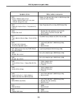
Ch4. Symptom-to-part index
Chapter 4. Symptom-to-part index
The symptom-to-part index in this section lists symptoms and errors and their possible causes.
The most likely cause is listed first.
Note
If replacing a part (FRU) does not solve the problem, put the original part back in the computer.
Do not replace a non-defective FRU.
Power system checkout
· To verify a symptom, do the following :
1. Power off the computer.
2. Remove the battery pack.
3. Connect the AC adapter.
4. Check that power is supplied when you power on the computer.
5. Power off the computer.
6. Disconnect the AC adapter and install the charged battery pack.
7. Check that the battery pack supplies power when you power on the computer.
· If you suspect a power problem, see the appropriate one of the following power supply checkouts :
1. Checking the AC adapter
2. Checking the operational charging
3. Checking the battery pack
4. Checking the backup battery
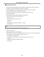
· Checking the AC adapter
If the power-on indicator does not turn on, check the power cord of the AC adapter for correct continuity
and installation.
If the computer does not charge during operation, go to “Checking operational charging.”
To check the AC adapter, do the following :
1. Unplug the AC adapter cable from the computer.
2. Measure the output voltage at the plug of the
AC adapter cable. See the following figure :
2
1
Ground
2
+18.05 ~ +19.95
1
Voltage (V dc)
Pin
Summary of Contents for LM60
Page 1: ...0 Service Manual LW60 70 LG Electronics ...
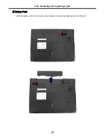
Page 48: ...47 Ch5 Removing and replacing a part 3 Disconnect cable 4 Disassemble the KBD Deck Assy ...
Page 54: ...53 Ch5 Removing and replacing a part ...
Page 56: ...55 Ch5 Removing and replacing a part 3 Disconnect connector and remove Speaker ...
Page 59: ...58 Ch5 Removing and replacing a part 3 Remove Main Board ...
Page 61: ...60 Ch5 Removing and replacing a part 2 Remove LCD Hook ...
Page 64: ...63 Ch5 Removing and replacing a part 6 Remove LCD panel ...
Page 66: ...65 Ch5 Removing and replacing a part ...
Page 67: ...66 Ch5 Removing and replacing a part 8 Remove WLAN Antenna ...
Page 77: ...76 Ch5 Removing and replacing a part 3 Disconnect cable 4 Disassemble the KBD Deck Assy ...
Page 82: ...81 Ch5 Removing and replacing a part ...
Page 84: ...83 Ch5 Removing and replacing a part 3 Disconnect connector and remove Speaker ...
Page 87: ...86 Ch5 Removing and replacing a part 2 Disconnect connector and remove Woofer ...
Page 91: ...90 Ch5 Removing and replacing a part 2 Remove LCD Hook ...
Page 94: ...93 Ch5 Removing and replacing a part 6 Remove LCD panel ...
Page 96: ...95 Ch5 Removing and replacing a part ...
Page 97: ...96 Ch5 Removing and replacing a part 8 Remove WLAN Antenna ...
Page 107: ...HWL29 HWL31 HWL10 HWL07 HWL03 15 4 HWL08 HWL34 HWL09 HWL27 HWL30 HWL31 HWL12 HWL11 ...
Page 108: ...HWL22 HWL29 HWL30 HWL23 HWL18 17 1 ...
Page 109: ...3 15 4 17 1 E XPLODE D VIE W HWL15 15 4 HWL14 15 4 HWL13 15 4 HWL33 HWM20 ...
Page 111: ...NRUB1 HWL32 HWL02 15 4 HWL17 17 1 ...
Page 114: ...HWM23 HWD01 17 1 HWD01 15 4 HWM30 HWM29 HWM31 HWM23 HWM33 ...
Page 115: ...HWD03 15 4 HWD04 17 1 HWD02 ...
Page 116: ...HWM10 15 4 HWM12 17 1 HWC09 HWM04 HWM06 HWM11 HWM05 HWM07 HWM22 HWM23 ...