background image

ENGLISH

1

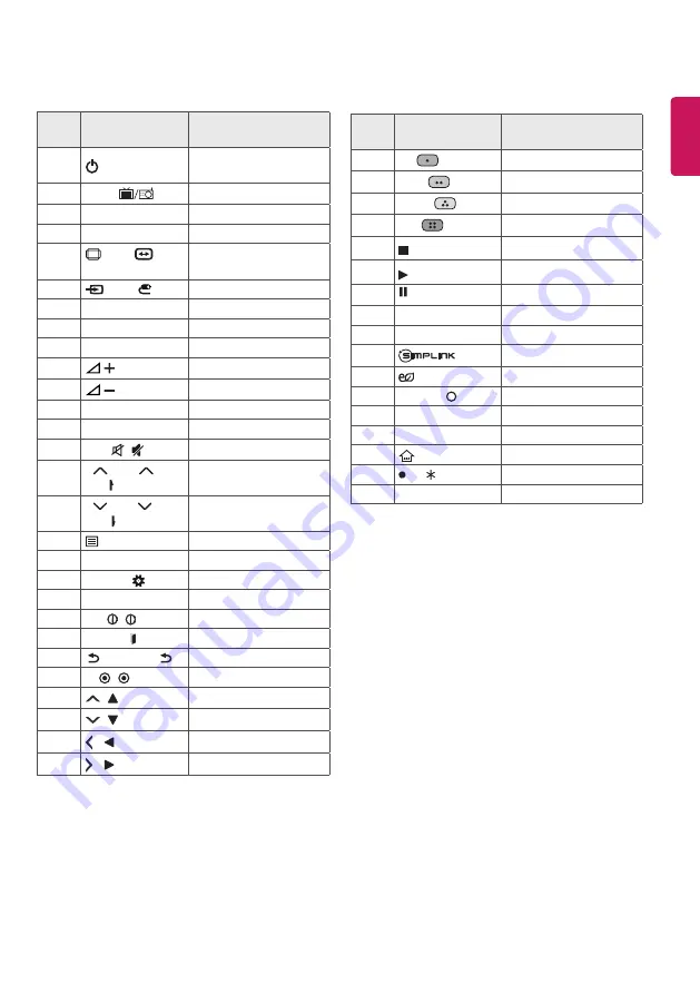
IR CODES

•  This feature is not available for all models.

Code 

(Hexa)

Function

Note

08


(POWER) 

Remote control Button  
(Power On/Off)

F0

TV/RAD 

Remote control Button

39

SUBTITLE

Remote control Button

91

AD

Remote control Button

79

 RATIO / 

 RATIO 

/ RATIO

Remote control Button

0B

 INPUT / 

Remote control Button

10-19 

Number Key 0-9

Remote control Button

53

LIST

Remote control Button

1A

Q.VIEW

Remote control Button

02


Remote control Button

03


Remote control Button

1E

FAV

Remote control Button

AB

GUIDE

Remote control Button

09

MUTE   / 

Remote control Button

00

P 


/ PAGE 


/


PAGE


Remote control Button

01

P   / PAGE   / 


PAGE 


Remote control Button

20

 TEXT

Remote control Button

21

T.OPT (T.Option)

Remote control Button

43     

SETTINGS / 

Remote control Button

45

Q.MENU

Remote control Button

AA

INFO   /   INFO

Remote control Button

5B

EXIT / EXIT 

Remote control Button

28

   BACK / BACK / 

Remote control Button

44

OK   /   OK

Remote control Button

40


/


Remote control Button

41


/


Remote control Button

07


/ 


Remote control Button

06


/ 


Remote control Button

Code 

(Hexa)

Function

Note

72

RED 

Remote control Button

71

GREEN 

Remote control Button

63

YELLOW 

Remote control Button

61

BLUE 

Remote control Button

B1


Remote control Button

B0

Remote control Button

BA

Remote control Button

8E

►►

Remote control Button

8F 

◄◄

Remote control Button

7E

Remote control Button

95

 ENERGY SAVING

Remote control Button

30

AV MODE  /   AV MODE Remote control Button

0C

PORTAL

Remote control Button

E8

ALARM

Remote control Button

7C


(HOME)

Remote control Button

BD


REC/

Remote control Button

0E

SLEEP

Remote control Button

Summary of Contents for 43LW30 Series

Page 1: ...AAA a b X 6 M4 X L20 32LW541 X 8 M4 X L20 43 49 55LW541 X 2 X 2 X 2 LED TV LW541 www lg com Depending on model ...

Page 2: ......

Page 3: ...1 a b 2 a b 5 4 B 43 49 55LW541 a b 3 B 43 49 55LW541 3 A 4 A 32LW541 32LW541 ...

Page 4: ...HDMI IN USB IN H P OUT ANTENNA CABLE IN MHL IN ...

Page 5: ...OPTICAL DIGITAL AUDIO OUT PCMCIA CARD SLOT CLOCK Satellite IN Depending on model ...

Page 6: ...VIDEO Y PB PR L MONO AUDIO R COMPONENT IN AV IN VIDEO L MONO AUDIO R VIDEO AUDIO VIDEO Y PB PR L MONO AUDIO R ...

Page 7: ...AUDIO OUT DVI OUT HDMIIN VIDEO Y PB PR L MONO AUDIO R HDMI DVI IN ...

Page 8: ...1 2 4 3 ...

Page 9: ......

Page 10: ... 0 A B C D E F F G 32LW541H TA 733 490 282 436 76 3 7 79 4 94 43LW541H TA 974 619 325 571 79 4 12 6 9 2 49LW541H TA 1107 695 325 645 79 4 15 2 11 8 55LW541H TA 1241 770 325 720 63 0 19 7 16 3 D B E C A F G ...

Page 11: ...ase read this manual carefully before operating your set and retain it for future reference Safety and Reference OWNER S MANUAL www lg com LED TV Disclaimer LG LED TV applies LCD screen with LED backlights ...

Page 12: ...dry the power plug completely or wipe dust off You may be electrocuted due to excess moisture Make sure to connect Mains cable to compliant AC mains socket with Grounded earth pin Except for devices which are not grounded on earth Otherwise possibility you may be electrocuted or injured Insert power cable plug completely into wall socket otherwise if not secured completely into socket fire ignitio...

Page 13: ... You may be electrocuted Depending on model Do not put or store inflammable substances near the product There is a danger of combustion explosion or fire due to careless handling of the inflammable substances Do not drop metallic objects such as coins hair pins chopsticks or wire into the product or inflammable objects such as paper and matches Children must pay particular attention Electrical sho...

Page 14: ...k malfunction or product deformation Never Disassemble the AC adapter or power cord This may result in fire or electric shock Be careful in handling the adapter to prevent any external shocks to it An external shock may cause damage to the adapter Make sure the power cord is connected securely to the power plug on theTV Depending on model CAUTION Install the product where no radio wave occurs Ther...

Page 15: ...ke sure the connecting cables are long enough Otherwise the product may fall over which may cause injury or damage the product Do not turn the product On Off by plugging in or unplugging the power plug to the wall outlet Do not use the power plug for switch It may cause mechanical failure or could give an electric shock Please follow the installation instructions below to prevent the product from ...

Page 16: ...ing the cable grab the plug and unplug it by pulling at the plug Don t pull at the cord to unplug the power cord from the power board as this could be hazardous When moving the product make sure you turn the power off first Then unplug the power cables antenna cables and all connecting cables TheTV set or power cord may be damaged which may create a fire hazard or cause electric shock When moving ...

Page 17: ...supplied with your product may vary depending on the model Product specifications or contents of this manual may be changed without prior notice due to upgrade of product functions For an optimal connection HDMI cables and USB devices should have bezels less than 10 mm thick and 18 mm width Use an extension cable that supports USB 2 0 if the USB cable or USB memory stick does not fit into yourTV s...

Page 18: ...d bottom of theTV frame firmly Make sure not to hold the transparent part speaker or speaker grill area When transporting a largeTV there should be at least 2 people When transporting theTV by hand hold theTV as shown in the following illustration When transporting theTV do not expose theTV to jolts or excessive vibration When transporting theTV keep theTV upright never turn theTV on its side or t...

Page 19: ...pright position on a table Leave a 10 cm minimum space from the wall for proper ventilation 10 cm 10 cm 10 cm 10cm 10 cm 2 Connect the power cord to a wall outlet CAUTION Do not place theTV near or on sources of heat as this may result in fire or other damage Attaching the TV to a desk This feature is not available for all models TheTV should be attached to a desk so it cannot be pulled in a forwa...

Page 20: ... additional accessories from your local dealer Adjusting the angle of the TV to suit view This feature is not available for all models Swivel 20 degrees to the left or right and adjust the angle of theTV to suit your view 20 20 CAUTION When adjusting the angle of the product watch out for your fingers Personal injury may occur if hands or fingers are pinched If the product is tilted too much it ma...

Page 21: ... item Adhesive label When installing the wall mounting bracket it is recommended to cover the stand hole using tape in order to prevent the influx of dust and insects Depending on model Stand hole How to use Dual Lock Only when the item of the following form is provided This feature is not available for all models Fix the set top box to theTV and use it when you want to 1 After removing the protec...

Page 22: ...ard Antenna connection Connect theTV to a wall antenna socket with an RF cable 75 Ω Use a signal splitter to use more than 2TVs If the image quality is poor install a signal amplifier properly to improve the image quality If the image quality is poor with an antenna connected try to realign the antenna in the correct direction An antenna cable and converter are not supplied Supported DTV Audio MPE...

Page 23: ...N port After making the physical connection theTV needs to be set up for network communication Connect the LAN port of the Modem or Router from Pro Centric server to the LAN port on theTV LAN Pro Centric Server Broadband Modem Broadband Modem Pro Centric Server Router CAUTION Do not connect a modular phone cable to the LAN port Since there are various connection methods please follow the specifica...

Page 24: ...wed programme B Adjusts the volume level Accesses your favourite programme list Shows programme guide 2 MUTE Mutes all sounds Depending on model Scrolls through the saved programmes Moves to the previous or next screen C D 3 3 3 4 4 C Teletext buttons These buttons are used for teletext 3 HOME Accesses the Home menu Depending on model 3 Views the information of the current programme and screen Dep...

Page 25: ...ive menu Views the information of the current programme and screen Navigation buttons up down left right Scrolls through menus or options Selects menus or options and confirms your input Accesses the main menus BACK Returns to the previous level Clears on screen displays and return toTV viewing Coloured buttons These access special functions in some menus Red Green Yellow Blue D Teletext buttons T...

Page 26: ...ution such as the cost of media shipping and handling upon email request to opensource lge com This offer is valid for three 3 years from the date on which you purchased the product Troubleshooting The software version can be updated for improvement in performance Customer needs to ensure the compatibility of customer s equipment with LGE software If needed please consult with LGE and upload revis...

Page 27: ...n 80 StorageTemperature 20 C to 60 C Storage Humidity Less than 85 1 Only Satellite models SatelliteTV Depending on model DigitalTV Depending on Country model AnalogueTV Depending on Country Television system DVB S S2 DVB C DVB T T2 PAL B B PAL B G PAL D K PAL I SECAM B G SECAM D K NTSC M Programme coverage C Band Ku Band VHF UHF VHF UHF CATV Maximum number of storable programmes 6 000 1 500 Only ...

Page 28: ... 720 x 400 31 46 70 08 640 x 480 31 46 59 94 800 x 600 37 87 60 31 1024 x 768 48 36 60 00 1152 x 864 54 34 60 05 1360 x 768 47 71 60 01 1280 x 1024 FHD only 63 98 60 02 1920 x 1080 FHD only 67 50 60 00 1 1 Except for 32LW30 32LW34 32LW54 Component port connecting information Component ports on theTV Y PB PR Video output ports on DVD player Y PB PR Y B Y R Y Y Cb Cr Y Pb Pr Signal Component 480i 57...

Page 29: ...2 XVID H 264 AVC Audio HE AAC Dolby Digital MPEG 1 Layer III MP3 LPCM motion JPEG Video MJPEG Audio LPCM ADPCM mpg mpeg mpe Video MPEG 1 MPEG 2 Audio MPEG 1 Layer I MPEG 1 Layer II Dolby Digital LPCM dat Video MPEG 1 MPEG 2 Audio MP2 flv Video Sorenson H 263 H 264 AVC Audio MP3 AAC HE AAC 3gp 3gp2 Video H 264 AVC MPEG 4 Part2 Audio AAC AMR NB WB Depending on model rm rmvb Video RV30 RV40 Audio Dol...

Page 30: ...x 8640 H Maximum ProgressiveType 1920 W x 1440 H Category BMP Available file type bmp Photo size Minimum 64 x 64 Maximum 9600 x 6400 Category PNG Available file type Interlace Non Interlace Photo size Minimum 64 x 64 Maximum Interlace 1200 x 800 Maximum Non Interlace 9600 x 6400 BMP and PNG format files may be slower to display than JPEG Non standard photo image file may not be displayed ...

Page 31: ...Record the model number and serial number of the TV Refer to the label on the back cover and quote this information to your dealer when requiring any service MODEL SERIAL ...

Page 32: ... Option Remote control Button 43 SETTINGS Remote control Button 45 Q MENU Remote control Button AA INFO INFO Remote control Button 5B EXIT EXIT Remote control Button 28 BACK BACK Remote control Button 44 OK OK Remote control Button 40 Remote control Button 41 Remote control Button 07 Remote control Button 06 Remote control Button Code Hexa Function Note 72 RED Remote control Button 71 GREEN Remote...

Page 33: ...rnally Connect the serial port of the control device to the RS 232C jack on the product back panel NOTE RS 232C connection cables are not supplied with the product Type of Connector D Sub 9 Pin Male 6 1 5 9 No Pin name 1 3 5V 2 RXD Receive data 3 TXD Transmit data 4 IR OUT fromTV 5 GND 6 No Connection 7 No Connection 5V available in some models 8 No Connection 9 No Connection 12V available in some...

Page 34: ...PC TV 2 3 3 2 5 5 4 6 6 4 7 7 8 8 D Sub 9 D Sub 9 RXD TXD GND DTR DSR RTS CTS TXD RXD GND DTR DSR RTS CTS Command Reference List Depending on model COMMAND1 COMMAND2 DATA Hexadecimal 01 Power k a 00 to 01 02 Aspect Ratio k c See p 4 03 Screen Mute k d See p 5 04 Volume Mute k e 00 to 01 05 Volume Control k f 00 to 64 06 Contrast k g 00 to 64 07 Brightness k h 00 to 64 08 Colour k i 00 to 64 09 Tin...

Page 35: ... The set transmits ACK acknowledgement based on this format when receiving abnormal data from non viable functions or communication errors Data 00 Illegal Code 01 Power Command k a To control Power On Off of the set Transmission k a Set ID Data Cr Data 00 Power Off 01 Power On Ack a Set ID OK NG Data x To ShowTV is Power On Off Transmission k a Set ID FF Cr Ack a Set ID OK NG Data x Similarly if o...

Page 36: ...e To control volume mute on off You can also adjust mute using the MUTE button on remote control Transmission k e Set ID Data Cr Data 00 Volume mute on Volume off 01 Volume mute off Volume on Ack e Set ID OK NG Data x 05 Volume Control Command k f To adjust volume You can also adjust volume with the volume buttons on remote control Transmission k f Set ID Data Cr Data Min 00 to Max 64 Refer to Rea...

Page 37: ... remotely Transmission k l Set ID Data Cr Data 00 OSD off 01 OSD on Ack l Set ID OK NG Data x 12 Remote control lock mode Command k m To lock the front panel controls on the monitor and remote control Transmission k m Set ID Data Cr Data 00 Lock off 01 Lock on Ack m Set ID OK NG Data x If you are not using the remote control use this mode When main power is on off external control lock is released...

Page 38: ...ically It works only in RGB PC mode Transmission j u Set ID Data Cr Data 01 To set Ack u Set ID OK NG Data x 17 Equalize Command j v To adjust equalize Transmission j v Set ID Data Cr MSB LSB Frequency Data 0 0 0 0 0 0 0 0 7 6 5 Frequency 4 3 2 1 0 Step 0 0 0 1st Band 0 0 0 0 0 0 decimal 0 0 1 2nd Band 0 0 0 0 1 1 decimal 0 1 0 3rd Band 0 1 1 4th Band 1 0 0 1 1 19 decimal 1 0 0 5th Band 1 0 1 0 0 ...

Page 39: ...x 21 Control Back Light Command m g To control the backlight Transmission m g Set ID Data Cr Data Min 00 to Max 64 Ack g Set ID OK NG Data x 22 Input select Command x b Main Picture Input To select input source for main picture Transmission x b Set ID Data Cr Data Structure MSB LSB ExternalInput InputNumber 0 0 0 0 0 0 0 0 External Input Data 0 0 0 0 DTV 0 0 0 1 Analogue 0 0 1 0 AV 0 1 0 0 Compone...

Page 40: ...ENGLISH 9 Real data mapping 00 Step0 A Step 10 Set ID 10 F Step 15 Set ID 15 10 Step 16 Set ID 16 64 Step 100 6E Step 110 73 Step 115 74 Step 116 CF Step 199 FE Step 254 FF Step 255 ...

Reviews: