1
300710168_002_C1 - 01/2018 - © Leybold
THERMOVAC Transmitter
TTR 91 R
Operating Manual 300710168_002_C1
Part Number: 230049V01
Page 1: ...1 300710168_002_C1 01 2018 Leybold THERMOVAC Transmitter TTR 91 R Operating Manual 300710168_002_C1 Part Number 230049V01 ...
Page 2: ...n mechanical 9 Installation Electrical 9 Recommended electrical connections 10 Operation 11 Pressure measurement 11 Gas dependency 13 Set point adjustment 14 Error monitoring 15 Bakeout 15 Maintenance 16 Atmosphere and vacuum adjustment 16 Atmosphere adjustment 16 Vacuum adjustment 17 Remote adjustment 17 Adjustment for new tube 17 Replace the gauge tube 18 FAQ Frequently Asked Questions 19 Storag...
Page 3: ...all work you are going to do and consider the safety instructions in this document Before beginning to work find out whether any vacuum components are contaminated Adhere to the relevant regulations and take the necessary precautions when handling contaminated parts Safety Precautions Failure to read message could result in damage to the equipment Refer to manual Failure to read message could resu...
Page 4: ...a Leybold Calibration and Service Centre for service and repair to ensure all of the safety features are maintained DANGER contaminated parts Contaminated parts can be detrimental to health and environment Before beginning to work find out whether any parts are contaminated Adhere to the relevant regulations and take the necessary precautions when handling contaminated parts DANGER Overpressure in...
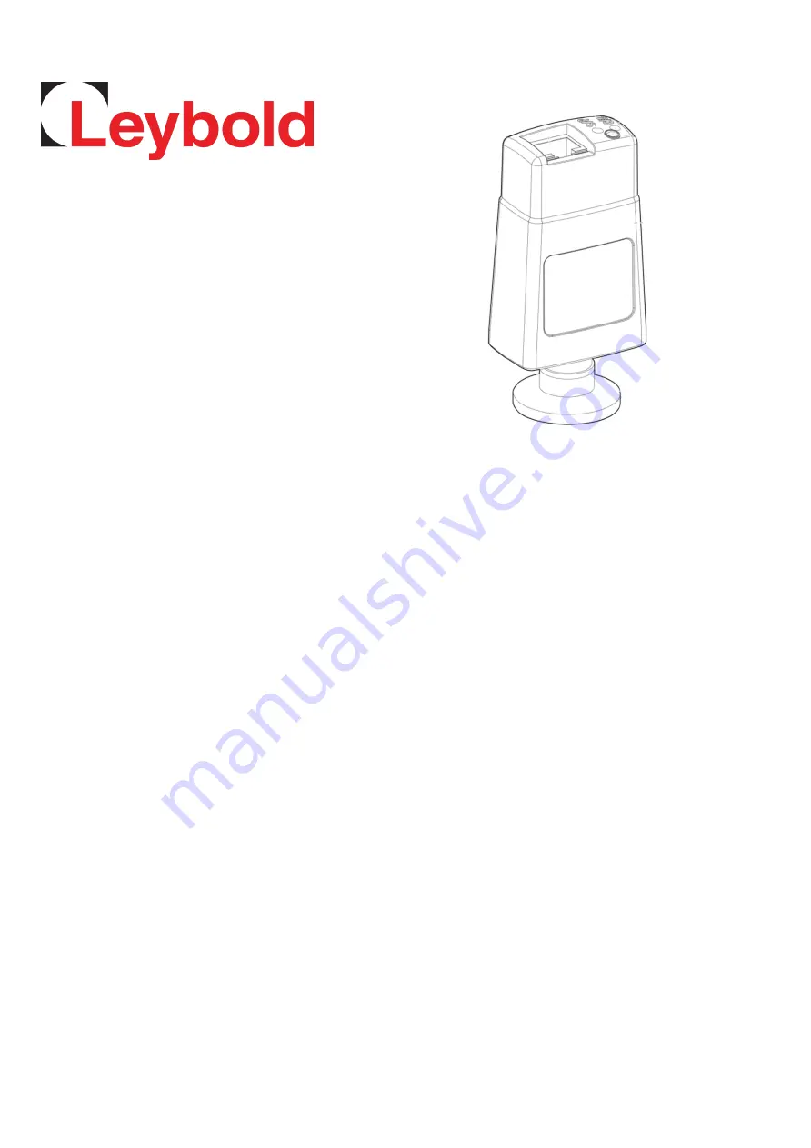
Page 5: ...n the pressure of gas surrounding the filament The TTR 91 R THERMOVAC transmitters can be used in a variety of applications as standalone units or with Graphix controllers P N 230680V01 230681V01 230682V01 and the Display controllers P N 230001 230024 230025 All THERMOVAC transmitters are backward compatible with Graphix Display and Center controllers A general view of the gauge is shown below The...
Page 6: ...000 m indoor use only Maximum internal pressure 10 bar absolute 9 bar gauge Filament temperature 100 C above ambient Materials exposed to vacuum Filament Tungsten Rhenium Tube Stainless Steel 316L 304L Filter Stainless Steel Other Glass Ni NiFe Stainless Steel Electrical data Supply voltage nominal 15 to 30 V d c minimum 13 5 V maximum 32 V Maximum power consumption 1 W Max inrush current 150 mA E...
Page 7: ...7 300710168_002_C1 01 2018 Leybold Dimensions mm ...
Page 8: ... Meter 12427 Cables Type A 20 Meter 12428 Cables Type A 30 Meter 12429 Cables Type A 50 Meter 12431 Cables Type A 75 Meter 12432 Cables Type A 100 Meter 12433 Accessories Centering Rings Stainless Steel 1 4305 with O Ring DN16 KF 88346 Centering Rings Stainless Steel with Sintered Metal Filter DN16 KF 88351 Clamping Rings Aluminum DN16 KF 18341 Centering Ring with fine filter DN 16 ISO KF 88396 Ca...
Page 9: ...hich is terminated in suitable RJ45 connectors These cables are available from Leybold Cable Type A The TTR91R is compatible with the GRAPHIX and DISPLAY controllers from Leybold The controllers will automatically recognize the gauge and display the measured pressure Installation Electrical Do not make any connection to the gauge identification pin pin 4 as this may cause the gauge to malfunction ...
Page 10: ...w open collector transistor suitable for driving a d c relay or control logic If you connect a relay you must use a suppression diode to protect the gauge from transient voltages generated when the relay is switched off Make a connection to pin 7 if you require remote calibration Momentarily 50ms connect pin 7 to pin 2 ground to automatically adjust the atmosphere or vacuum reading Refer to the Ma...
Page 11: ...en turn green if the gauge is operating correctly or red if an error is detected Refer to the fault finding guide If the gauge is connected to a Leybold controller the display will indicate the measured pressure The TTR 91 R provides a voltage output which is a function of pressure The output voltage scales with 1 296V dc decade Conversion formulae 𝑃𝑚𝑏𝑎𝑟 10 𝑉 6 143 1 286 𝑉 𝑙𝑜𝑔10 𝑃𝑚𝑏𝑎𝑟 1 286 6 143 ...
Page 12: ...4 00E 01 5 631 6 00E 01 8 430 3 00E 03 2 899 5 00E 01 5 756 7 00E 01 8 516 4 00E 03 3 059 6 00E 01 5 858 8 00E 01 8 590 5 00E 03 3 184 7 00E 01 5 944 9 00E 01 8 656 6 00E 03 3 286 8 00E 01 6 018 1 00E 02 8 715 7 00E 03 3 372 9 00E 01 6 084 1 50E 02 8 941 8 00E 03 3 446 1 00E 00 6 143 2 00E 02 9 102 9 00E 03 3 512 1 50E 00 6 369 3 00E 02 9 329 1 00E 02 3 571 2 00E 00 6 530 4 00E 02 9 489 1 50E 02 3...
Page 13: ...ding The graph below shows the conversion for 6 common gases nitrogen argon carbon dioxide helium krypton and neon Gas dependency of TTR 91 R For pressures below 1 mbar a simple calibration factor can be used to correct for different gas types Gas Calibration Factors GCFs for common gases are shown below True pressure GCF x indicated pressure Gas calibration factors below 1 mbar Gas GCF He 1 1 Ne ...
Page 14: ...rn of when the pressure rises to 500 mV above the set point To adjust the set point threshold push the S P button and hold it down for more than three seconds The threshold value will increase steadily Release the button when you reach the required value To make finer adjustment release the button just before the required value is reached and immediately push the button as many times as required E...
Page 15: ...er to the FAQ section Error indication Error condition Output V Broken filament or tube removed 0 5 Calibration error 0 5 Bakeout In some UHV applications it is desirable to bake the vacuum system components in order to achieve a lower base pressure The tube of the TTR 91 R can be baked to 150 C but the electronics housing must be removed Referring to the figure in section 6 7 remove the electroni...
Page 16: ...ncy with which they should be repeated will vary depending on the level and nature of the contamination associated with the process Adjustment of TTR 91 R Atmosphere adjustment 1 Switch on the power supply to the TTR 91 R and allow it to operate at atmospheric pressure for at least 10 minutes Ensure that the green status LED is lit 2 Press the CAL button The status LED turn amber and the gauge wil...
Page 17: ...y close the remote switch instead of using the CAL button on the gauge Adjustment for new tube If a replacement tube is fitted to the gauge it will be necessary to adjust the gauge to match the new tube Note that this is not required unless a new tube is fitted and it is always necessary to perform a vacuum adjustment afterwards 1 Switch on the power supply to the TTR 91 R 2 With the gauge at atmo...
Page 18: ...e tube Unplug the electrical cable vent the vacuum system to atmospheric pressure and remove the gauge from the vacuum system Pull the retaining clip from side of gauge Pull the tube from the electronics housing Fit the replacement tube into electronics housing noting the correct alignment Refit the retaining clip Whenever a new tube is fitted it is necessary to adjust the gauge to match the new t...
Page 19: ...or good vacuum New tube has been fitted Perform Adjustment for new tube Tube has drifted outside permissible limits and can no longer be adjusted Replace the tube Tube is missing Fit the tube and remove then re insert the electrical connector Filament is broken Replace the tube Storage and disposal Dispose of the TTR 91 R and any components safely in accordance with all local and national safety a...
Page 20: ...hed the contractor is to be informed about any possible contamination of the compressor vacuum pump or component sent in for servicing Based on this information the contractor will be able to take the necessary safety precautions Preparation before dispatch Before shipping any parts the user must complete the following declaration and add it to the dispatch papers All dispatch instructions laid do...
Page 21: ...21 300710168_002_C1 01 2018 Leybold ...
Page 22: ...U Directive RoHS 2011 65 EU The following harmonized standards have been applied EN 61010 1 2010 Safety requirements for electrical equipment for measurement control and laboratory use Part 1 General requirements EN 61326 1 2013 Electrical equipment for measurement control and laboratory use EMC requirements Part 1 General requirements Emissions Group 1 Class B Immunity Industrial electromagnetic ...
Page 23: ...n at least one of the homogeneous materials used which are above the limit requirement in GB T 26572 as detailed in the declaration table below These parts can safely be used for the environmental protection use period as indicated NOTE This product is EU RoHS complaint the following Exemptions apply 6 c Copper alloy containing up to 4 lead by weight 7 c I Electrical and electronic components cont...
Page 24: ...24 300710168_002_C1 01 2018 Leybold ...