


The Hibernate mode can be entered in any of the following methods:
•
Using the Hibernate Timeout
•
Using the Schedule Power modes
•
Using the Sleep/Hibernate button
Factory default Hibernate Timeout for this product in all countries or regions
3 days
The amount of time the printer waits after a job is printed before it enters Hibernate mode can be modified
between one hour and one month.
Off mode
If this product has an off mode which still consumes a small amount of power, then to completely stop product
power consumption, disconnect the power supply cord from the electrical outlet.
Total energy usage
It is sometimes helpful to calculate the total product energy usage. Since power consumption claims are
provided in power units of Watts, the power consumption should be multiplied by the time the product spends
in each mode in order to calculate energy usage. The total product energy usage is the sum of each mode's
energy usage.
Selecting a location for the printer
When selecting a location for the printer, leave enough room to open trays, covers, and doors and to install
hardware options.
•
Set up the printer near an electrical outlet.
CAUTION—POTENTIAL INJURY:
To avoid the risk of fire or electrical shock, connect the power cord
to an appropriately rated and properly grounded electrical outlet that is near the product and easily
accessible.
CAUTION—SHOCK HAZARD:
To avoid the risk of electrical shock, do not place or use this product
near water or wet locations.
•
Make sure that airflow in the room meets the latest revision of the ASHRAE 62 standard or the CEN Technical
Committee 156 standard.
•
Provide a flat, sturdy, and stable surface.
•
Keep the printer:
–
Clean, dry, and free of dust.
–
Away from stray staples and paper clips.
–
Away from the direct airflow of air conditioners, heaters, or ventilators.
–
Free from direct sunlight and humidity extremes.
•
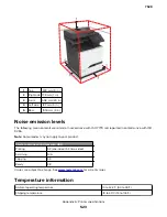
Observe the recommended temperatures and avoid fluctuations:
Ambient temperature 10 to 32.2°C (50 to 90°F)
Storage temperature
-40 to 40°C (-40 to 104°F)
•
Allow the following recommended amount of space around the printer for proper ventilation:
7528
Appendix A: Printer specifications
522
Summary of Contents for XC4150
Page 34: ...7528 34 ...
Page 276: ...7528 276 ...
Page 294: ...Scan SE Scanner Info 7528 Service menus 294 ...
Page 317: ...3 Remove the screw B from the lower left side of the cover B 7528 Repair information 317 ...
Page 320: ...3 Remove the three screws A 7528 Repair information 320 ...
Page 327: ...3 Remove the E clip B 4 Remove the E clip C 7528 Repair information 327 ...
Page 358: ...5 Remove the two screws D from under the gear box 7528 Repair information 358 ...
Page 360: ...3 Disconnect the cable A from the LVPS 7528 Repair information 360 ...
Page 370: ...3 Disconnect the motor cable A A 7528 Repair information 370 ...
Page 371: ...4 Remove the four screws B and then remove the motor B 7528 Repair information 371 ...
Page 374: ...4 Disconnect the cable B 5 Remove the screw C securing the HVPS C 7528 Repair information 374 ...
Page 400: ...14 Remove the clip M and then remove the spacer 7528 Repair information 400 ...
Page 403: ...7528 Repair information 403 ...
Page 414: ...5 Remove the screw C from the printhead 7528 Repair information 414 ...
Page 429: ...8 Route the ADF cable through the flatbed 9 Remove the ADF 7528 Repair information 429 ...
Page 437: ...7 Disconnect the two cables B on the controller board 7528 Repair information 437 ...
Page 443: ...5 Remove the screw D and then remove the scanner tilt D 7528 Repair information 443 ...
Page 478: ...7528 478 ...
Page 485: ...7528 485 ...
Page 487: ...Assembly 1 Covers 1 2 4 6 7 8 9 1 14 10 3 5 13 13 11 11 12 7528 Parts catalog 487 ...
Page 489: ...Assembly 2 Covers 2 14 7528 Parts catalog 489 ...
Page 491: ...Assembly 3 Control panel 5 4 3 2 1 7528 Parts catalog 491 ...
Page 493: ...Assembly 4 ADF and flatbed 1 3 11 10 4 9 5 6 7 8 2 7528 Parts catalog 493 ...
Page 495: ...Assembly 5 Fuser 1 7528 Parts catalog 495 ...
Page 497: ...Assembly 6 Transfer module 1 2 7528 Parts catalog 497 ...
Page 499: ...Assembly 7 Paper feed 8 2 1 2 4 7 3 5 5 6 7528 Parts catalog 499 ...
Page 501: ...Assembly 8 Paper path 1 8 6 2 3 1 10 5 7 9 4 7528 Parts catalog 501 ...
Page 503: ...Assembly 9 Paper path 2 1 4 2 5 10 3 6 9 7 8 7528 Parts catalog 503 ...
Page 505: ...Assembly 10 Duplex 9 8 3 3 7 6 1 1 2 4 5 7528 Parts catalog 505 ...
Page 507: ...Assembly 11 Electrical 16 2 3 4 5 7 8 9 11 12 13 15 6 1 14 10 7528 Parts catalog 507 ...
Page 510: ...7528 Parts catalog 510 ...
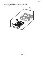
Page 511: ...Assembly 12 550 sheet tray option 1 2 1 7528 Parts catalog 511 ...
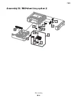
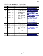
Page 513: ...Assembly 13 550 sheet tray option 2 1 2 3 4 12 11 6 13 5 9 10 7 8 7528 Parts catalog 513 ...
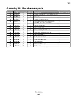
Page 515: ...Assembly 14 Adjustable stand 2 2 3 3 1 7528 Parts catalog 515 ...
Page 518: ...7528 Parts catalog 518 ...
Page 520: ...7528 520 ...
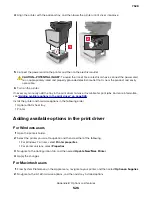
Page 527: ...3 Apply the changes 7528 Appendix B Options and features 527 ...
Page 528: ...7528 528 ...
Page 554: ...7528 554 ...
Page 568: ...7528 Part number index 568 ...
Page 574: ...7528 Part name index 574 ...


