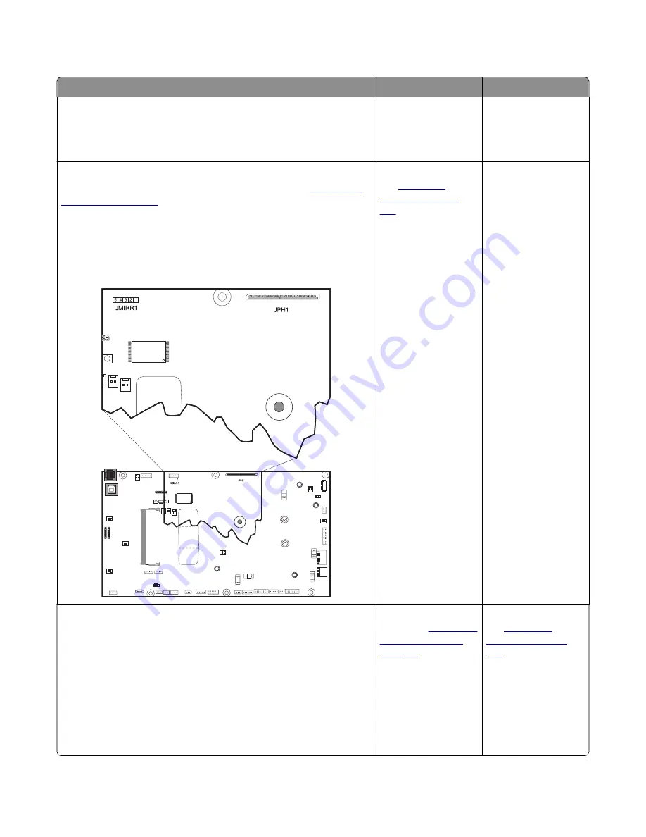
Printhead service check
Actions
Yes
No
Step 1
POR the printer.
Does this solve the problem?
The problem is solved. Go to step 2.
Step 2
Turn the printer off, and then remove the rear cover. See
Check the cables at JMIRR1 and JPH1 on the controller board for proper
connection, the printhead cable for pinch points, and the cable or
connector for any other damage.
Is the cable damaged?
Replace the printhead.
See
Go to step 3.
Step 3
Turn the printer on, and then wait until the printer posts an error. Using
a voltmeter, check the following values at JMIRR1:
Pin 1: +5 V dc
Pin 2: +3.3 V dc
Pin 3: +5 V dc
Pin 4: Ground
Pin 5: +24 V dc
Are the values approximately correct?
Replace the controller
board. See
.
Replace the printhead.
See
7527
Diagnostic information
89
Summary of Contents for XC2132
Page 18: ...7527 18 ...
Page 22: ...7527 22 ...
Page 34: ...7527 34 ...
Page 54: ...2 Open the top door 7527 Diagnostic information 54 ...
Page 184: ...7527 184 ...
Page 226: ...7527 226 ...
Page 314: ...5 Disconnect the belt C 6 Disconnect the fan and remove 7527 Repair information 314 ...
Page 345: ...Component locations Controller board CX310 models 7527 Component locations 345 ...
Page 346: ...CX410 models 7527 Component locations 346 ...
Page 352: ...7527 352 ...
Page 359: ...7527 359 ...
Page 361: ...Assembly 1 Covers 7527 Parts catalog 361 ...
Page 363: ...Assembly 2 Scanner 7527 Parts catalog 363 ...
Page 365: ...Assembly 3 Paperpath 7527 Parts catalog 365 ...
Page 368: ...7527 Parts catalog 368 ...
Page 369: ...Assembly 4 Operator panels 7527 Parts catalog 369 ...
Page 372: ...7527 Parts catalog 372 ...
Page 373: ...Assembly 5 Electronics 7527 Parts catalog 373 ...
Page 376: ...7527 Parts catalog 376 ...
Page 377: ...Assembly 6 Cables and sensors 7527 Parts catalog 377 ...
Page 379: ...Assembly 7 Media drawers and trays 7527 Parts catalog 379 ...
Page 382: ...7527 382 ...
Page 390: ...7527 390 ...
Page 404: ...7527 404 ...
Page 422: ...7527 Part number index 422 ...
Page 428: ...7527 Part name index 428 ...


