Diagnostic Information 2-16
4049-XXX
the LVPS voltages are correct. Turn the power back off and, one at a
time, reconnect the engine board cables, powering on in between
each connection and checking the voltages. The connection which
causes the voltages to be wrong indicates which component is bad.
Repair or replace the failing component or cable as necessary.
Duplex
The duplex unit should home — the front shafts should turn and the
input deflector should move — immediately when you install the
duplex unit with the printer already powered on, or just before the
[Ready] screen is displayed when you POR the printer with the
duplex unit installed. This means the duplex unit and the printer are
communicating and thus the printer engine board, duplex unit sys-
tem board, and the cables between them are all good.
If the duplex unit does not home immediately but homes after 5 or 6
seconds, the duplex unit is rec34 VDC from the printer but is
not communicating with the printer. The duplex unit homes on its
own as a signal that it is functional.
If the duplex unit does not home at all, it is either damaged or is not
rec34 VDC from the printer.
To check the connection from the printer engine board to the duplex
system board, remove the printer RIP Board. Remove the duplex top
cover and table cover, and reinstall the duplex unit. Engine board J3-
2 should have continuity with the duplex system board J5-1, J3-3
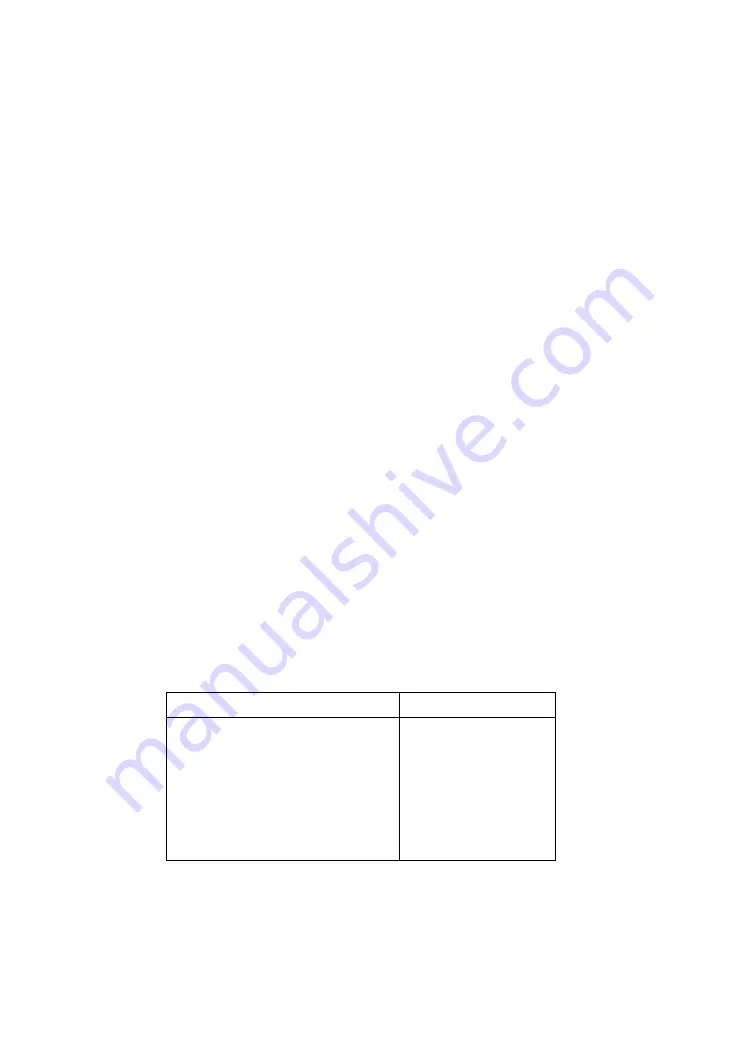
with J5-2, and so on. With power on, you should have the following
voltages:
Connector
Voltage to Ground
Engine Board
J3-3
+34 VDC
J3-5
+5 VDC
J3-7
+5 VDC
Duplex System
Board
J5-2
+34 VDC
J5-4
+5 VDC
J5-6
+5 VDC
Summary of Contents for Optra 4049 Series
Page 16: ...xvi Service Manual 4049 XXX Chinese Laser Notice Korean Laser Notice ...
Page 22: ...xxii Service Manual 4049 XXX ...
Page 90: ...4 11 4049 XXX ...
Page 92: ...4 13 4049 XXX ...
Page 104: ...4 25 4049 XXX ...
Page 106: ...4 27 4049 XXX ...
Page 128: ...5 2 4049 XXX Gear Train ...
Page 134: ...5 8 4049 XXX Operator Panel Output Bin Sensor Cable Op Panel Cable Connector Pin 1 Pin 1 ...
Page 144: ...7 2 4049 XXX Assembly 1 Covers ...
Page 146: ...7 4 4049 XXX Assembly 2 Lower Frame ...
Page 148: ...7 6 4049 XXX Assembly 3 Upper Frame ...
Page 150: ...7 8 4049 XXX Assembly 4 Printhead ...
Page 152: ...7 10 4049 XXX Assembly 5 Paper Feed ...
Page 154: ...7 12 4049 XXX Assembly 5 Paper Feed Continued ...
Page 156: ...7 14 4049 XXX Assembly 6 Paper Feed Alignment Gears ...
Page 158: ...7 16 4049 XXX Assembly 7 Paper Feed Drive ...
Page 160: ...7 18 4049 XXX Assembly 8 Standard Paper Tray 200 Sheet ...
Page 162: ...7 20 4049 XXX Assembly 9 Paper Tray 500 Sheet ...
Page 164: ...7 22 4049 XXX Assembly 10 Base for Paper Drawer 500 Sheet ...
Page 166: ...7 24 4049 XXX Assembly 11 Second Paper Drawer 200 Sheet ...
Page 168: ...7 26 4049 XXX Assembly 12 Optional Paper Drawer 500 Sheet ...
Page 170: ...7 28 4049 XXX Assembly 13 Fuser ...
Page 172: ...7 30 4049 XXX Assembly 13 Fuser Continued ...
Page 174: ...7 32 4049 XXX Assembly 14 Electronics ...
Page 176: ...7 34 4049 XXX Assembly 14 Electronics Continued ...
Page 178: ...7 36 4049 XXX Assembly 15 Transfer Roll ...
Page 182: ...7 40 4049 XXX Assembly 17 Envelope and 100 Sheet Auxiliary Feeder ...
Page 184: ...7 42 4049 XXX Assembly 18 Dual Rear Feeder ...
Page 186: ...7 44 4049 XXX Assembly 19 High Capacity Feeder ...


