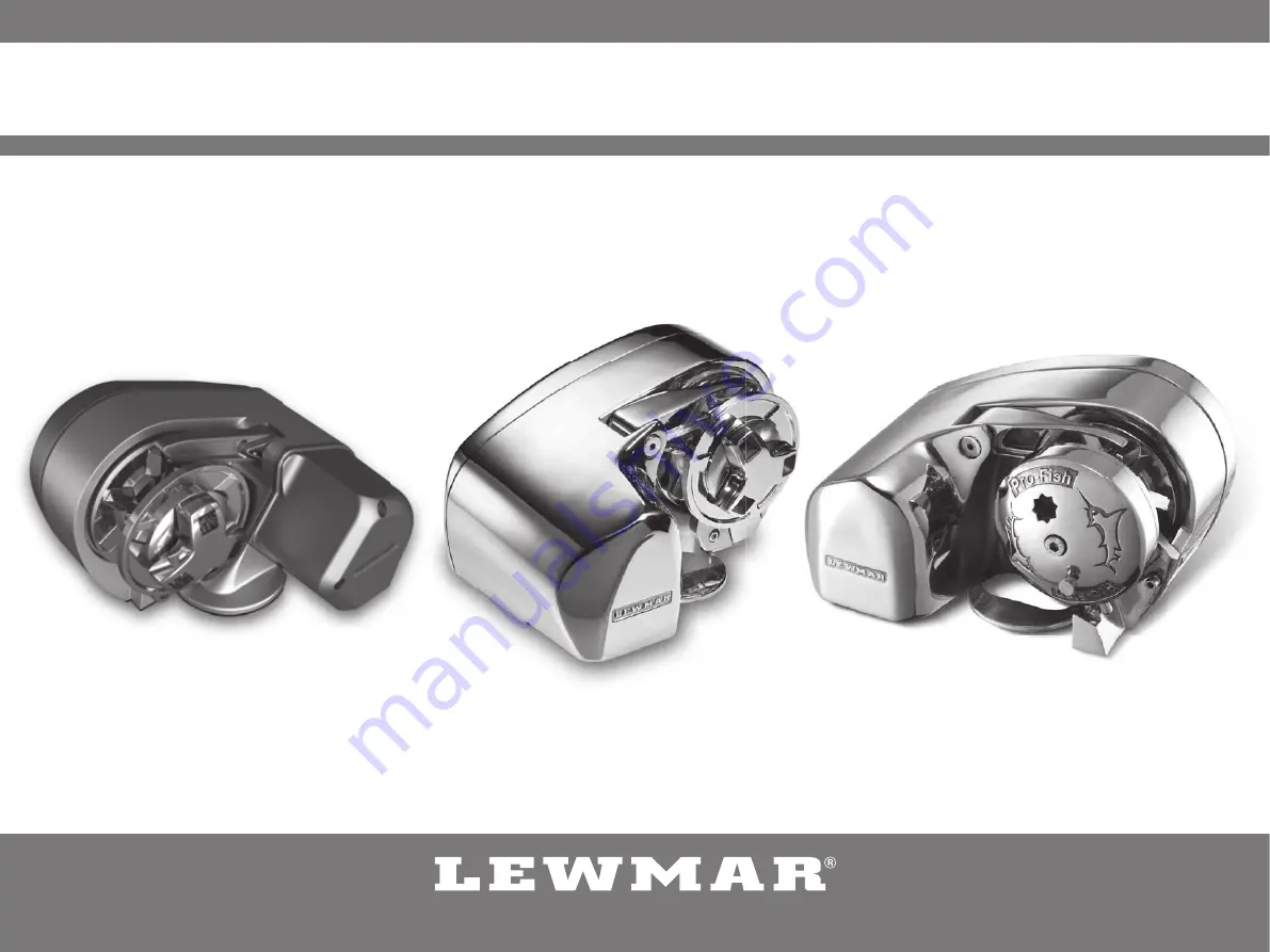
Lewmar Pro-Sport/Series/Fish Windlass
65001242 Issue 3
Owner’s Installation, Operation & Basic Servicing Manual
Page 1: ...Lewmar Pro Sport Series Fish Windlass 65001242 Issue 3 Owner s Installation Operation Basic Servicing Manual...
Page 2: ...boats because an anchor accidentally deploying while under way can cause considerable damage An anchor windlass is mounted in the most exposed position on a vessel and is thus subject to severe atmosp...
Page 3: ...chor 1 Lewmar recommends a minimum deck thickness of 25mm 1 M8 Studs suit deck and packing thickness of 25 60mm 1 21 4 3 4 1 3 5 1 3 Installation 25 60 mm 1 21 4 3 1 Basic requirements Each installati...
Page 4: ...l and bulkhead clearance 1 Lead from the roller should be fed horizontally back to the top of the gypsy and along its centre line within 6 There must be sufficient vertical fall for the chain or rope...
Page 5: ...ort Using a 10mm 3 8 diameter drill make the three holes for the mounting studs and one for the cables With a 76mm 3 diameter hole saw make one hole for the rode to pass through 2 When all the holes h...
Page 6: ...fitting 1 Fit windlass to deck Trim the studs back to 6mm 1 4 below the fully tightened nuts to prevent snagging anchor rope chain if necessary NOTE If using silicone or other rubbery type sealant it...
Page 7: ...the vessel Windlass performance is directly related to cable size and length Voltage drop over the complete wiring run must not exceed 10 4 2 Wiring Plan the installation to suit the controls and give...
Page 8: ...ntrol box V 0 7 m 0 23 ft 7 15 m 23 50 ft 15 22 m 50 73 ft A Pro Series 700 12 10 mm2 8 AWG 16 mm2 6 AWG 25 mm2 4 AWG 50A 68000348 68000939 68000965 68000963 Pro Series 1000 12 10 mm2 6 AWG 25 mm2 4 A...
Page 9: ...es 4 Electrical Wiring ON A B NOTE Cable Colours A Black B Red Switch wire thickness 1 5 mm2 16 AWG Electric Switches See Chart UP DOWN Remote Handheld Control See Chart Rocker Switch 68000593 UP DOWN...
Page 10: ...es 4 Electrical Wiring ON A B NOTE Cable Colours A Black B Red Switch wire thickness 1 5 mm2 16 AWG Electric Switches See Chart UP DOWN Remote Handheld Control See Chart Rocker Switch 68000593 UP DOWN...
Page 11: ...sories ON A B NOTE Cable Colours A Black B Red Switch wire thickness 1 5 mm2 16 AWG 4 Electrical Wiring Electric Switches See Chart UP DOWN Remote Handheld Control See Chart Rocker Switch 68000593 UP...
Page 12: ...ains in the down position 2 Release any anchor locks 3 When safe insert the Lewmar wrench in to the capstan drive cap Rotate clockwise to grip the gypsy and anticlockwise to free the gypsy controlling...
Page 13: ...drive cap Rotate clockwise to grip the gypsy and anticlockwise to free the gypsy controlling the rate of descent of the anchor Lock the clutch by turning the drive cap clockwise and engage the anchor...
Page 14: ...cap is tight so the clutch is locked 2 Release any anchor locks and when safe insert the Lewmar wrench or a standard 12mm 1 2 drive rachet into the socket end of the driveshaft on the opposite site o...
Page 15: ...n a longer clutch re engagement time during the next UP command If using a rope chain rode motor astern to create the desired scope Once scope has been created press the UP button continuously until f...
Page 16: ...ain stopper 1 When anchoring power rode out allowing the vessel to take up stern away preventing the rode tangling with anchor Use this method for mooring stern first to a jetty 2 To aid recovery unde...
Page 17: ...everse order Clean and lightly grease components When re assembling the cone and gypsy add a small smear of grease to the contact surfaces WARNING Isolate the windlass using circuit breaker isolator W...
Page 18: ...2 66000635 Gears and Shaft Kit 11 1 13 1 14 2 15 2 16 1 22 1 23 1 25 1 27 1 30 1 66000636 Compound Gear Kit 22 1 66000107 Motor 12 V 11 1 32 1 10 3 12 1 13 1 35 2 66000108 Fastening Kit Metric 47 1 4...
Page 19: ...n 2 1 6052904 12V 150W Electric Motor 25 1 7 3 6052945 Compound Gear Assembly 10 1 66000643 P Sport Fastner Kit 1 3 7 3 8 1 9 1 13 2 24 1 33 8 34 3 66000644 P Sport Mounting Kit 1 3 17 1 29 3 30 3 660...
Page 20: ...m DIN 766 7 0 276 22 0 866 23 8 0 937 1 4 ISO G4 7 0 276 21 3 0 840 24 4 0 962 1 4 BBB 7 14 0 281 22 1 0 870 25 2 0 992 RC0860 Gypsy No 504 14 16 mm 9 16 5 8 3 Strand and 8 Plait 5 8 only 8 mm DIN 766...
Page 21: ...P W D D mm D inch P mm P inch W mm W inch RC0670 Gypsy No 502 12 mm 1 2 3 Strand and 8 Plait 6 mm DIN 766 6 0 236 18 5 0 728 20 4 0 803 RC0761 Gypsy No 503 12 mm 1 2 3 Strand and 8 Plait 7 mm DIN 766...
Page 22: ...7 3 Pro Series Fish deck template guide 7 Specifications...
Page 23: ...7 4 Pro Sport deck template guide 7 Specifications...
Page 24: ...tal Weight Circuit Breaker V W kg lb m min ft min kg lb A kg lb A Pro Series 700 12 500 320 700 32 105 79 175 35 8 5 19 50 Pro Series 1000 12 700 454 1000 32 105 114 250 50 9 5 21 70 Pr Fish 700 12 50...
Page 25: ...ies regarding the fitness for purpose use nature or satisfactory quality of the products ii Where applicable law does not permit a statutory or implied warranty to be excluded then such warranty if pe...