background image


287

 - 

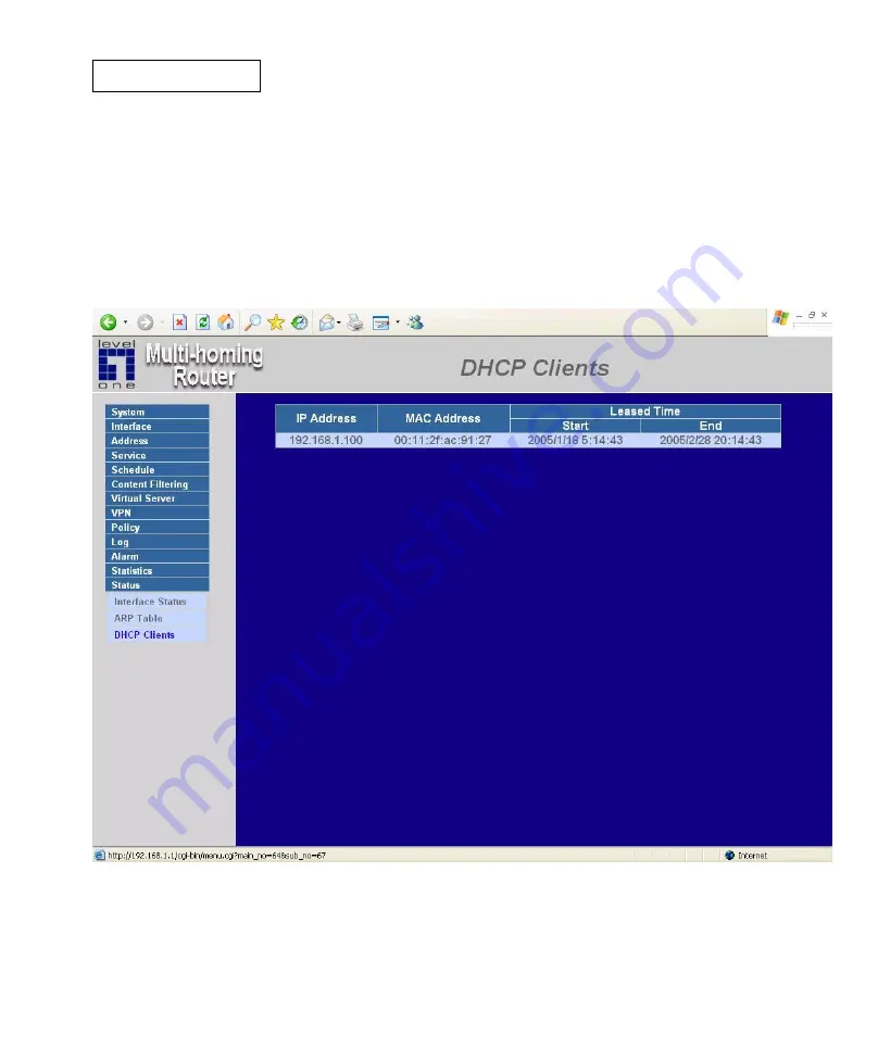
DHCP Clients 

 
Entering the DHCP Clients window 


Click on 

Status

 in the menu bar, then click on 

DHCP Clients 

below it.    A window will appear 

displaying the table of DHCP clients that are connected to the device.    The table will list host 

computers on the LAN network that obtain its IP address from the Multi-

Homing Gateway‟s 

DHCP server function. 


IP Address:

    the IP address of the LAN host computer 

MAC Address:

    MAC address of the LAN host computer 

Leased Time:

    The Start and End time of the DHCP lease for the LAN host computer. 

Summary of Contents for FBR-2000

Page 1: ...LevelOne FBR 2000 2 WAN Load Balance Broadband Router User Manual V1 3...

Page 2: ...ttings 20 Add Multiple Subnet NAT Mode 21 Modify Multiple Subnet 22 Delete Multiple Subnet 23 Hacker Alert 30 Auto Detect functions 30 Route Table 34 Entering the Route Table screen 34 Route Table fun...

Page 3: ...DMZ 66 Address 68 LAN 69 Entering the LAN window 69 Adding a new LAN Address 70 Modifying an LAN Address 71 Removing an LAN Address 72 LAN Group 73 Entering the LAN Group window 73 Modifying an LAN G...

Page 4: ...ssing the Group window 100 Adding Service Groups 101 Modifying Service Groups 102 Removing Service Groups 103 Schedule 104 Accessing the Schedule window 105 Adding a new Schedule 106 Modifying a Sched...

Page 5: ...odifying the Virtual Server configurations 132 VPN 135 IPSec Autokey 136 PPTP Server 218 Entering the PPTP Server window 218 Modifying PPTP Server Design 219 Adding PPTP Server 220 Modifying PPTP Serv...

Page 6: ...vent Log 262 Entering the Event Log window 262 Downloading the Event Logs 263 Clearing the Event Logs 264 Download Logs 266 Log Backup 268 Enable Log Mail Support Syslog Message 269 Disable Log Mail S...

Page 7: ...by Time 280 Policy Statistics 282 Entering the Statistics window 282 Entering the Policy Statistics 283 Status 284 Interface Status 285 Entering the Interface Status window 285 ARP Table 286 Entering...

Page 8: ...even sub functions under System are Admin Setting Date Time Multiple Subnet Hack Alert Route Table DHCP DNS Proxy Dynamic DNS Logout and Software Update Admin has control of user access to the Multi H...

Page 9: ...mail server of the organization easily by its domain name providing that the Administrator has set up Virtual Server or Mapped IP settings correctly However for the users in the Internal network thei...

Page 10: ...s is permitted to manage the Multi Homing Gateway Logout Administrator logs out the Multi Homing Gateway This function protects your system while you are away Software Update Administrators may visit...

Page 11: ...he Multi Homing Gateway The user admin cannot be removed Privilege The privileges of Administrators Admin or Sub Admin The username of the main Administrator is Administrator with read write privilege...

Page 12: ...to create a new Sub Administrator Step 2 In the Add New Sub Administrator window Sub Admin Name enter the username of new Sub Admin Password enter a password for the new Sub Admin Confirm Password ent...

Page 13: ...and click on Modify in the Configure field Step 2 The Modify Administrator Password window will appear Enter in the required information Password enter original password New Password enter new passwor...

Page 14: ...e Administration table locate the Administrator name you want to edit and click on the Remove option in the Configure field Step 2 The Remove confirmation pop up box will appear Step 3 Click OK to rem...

Page 15: ...an Administrator computer or anywhere on the network or restore a configuration file to the device or restore the Multi Homing Gateway back to default factory settings Entering the Settings window Cl...

Page 16: ...ing Gateway Configuration click on the Download button next to Export System Settings to Client Step 2 When the File Download pop up window appears choose the destination place in which to save the ex...

Page 17: ...click on the Browse button next to Import System Settings When the Choose File pop up window appears select the file to which contains the saved Multi Homing Gateway Settings then click OK Step 2 Cli...

Page 18: ...11 Restoring Factory Default Settings Step 1 Select Reset Factory Settings under Multi Homing Gateway Configuration Step 2 Click OK at the bottom right of the screen to restore the factory settings...

Page 19: ...nditions occur Step 2 Device Name Enter the Device Name Step 3 Sender Address Required by some ISPs Enter the Sender Address Some ISPs need Required Step 4 SMTP Server IP Enter SMTP server s IP addres...

Page 20: ...face Remote UI management The administrator can change the port number used by HTTP port anytime Remote UI management Step 1 Set Web Management WAN Interface The administrator can change the port numb...

Page 21: ...14 MTU set networking packet length The administrator can modify the networking packet length Step 1 MTU Setting The administrator can modify the networking packet length...

Page 22: ...ulti Homing Gateway Packets Log Select this option to the device s To Multi Homing Gateway Packets Log Once this function is enabled every packet to this appliance will be recorded for system manager...

Page 23: ...he Multi Homing Gateway will be reboot Step 1 Click Setting in the Administration menu to enter the settings window Step 2 Reboot Multi Homing Gateway Click Reboot Step 3 A confirmation pop up box wil...

Page 24: ...ion by checking the box Step 2 Click the down arrow to select the offset time from GMT Step 3 Enter the Server IP Address or Server name with which you want to synchronize Step 4 Update system clock e...

Page 25: ...18...

Page 26: ...AN 1 2 Service department subnet work 192 168 2 11 24 Internal 168 85 88 252 WAN 1 3 Sales depam ent subnet work 192 168 3 11 24 Internal 168 85 88 251 WAN 1 4 Procurement department subnet work 192 1...

Page 27: ...ltiple Subnet WAN Interface IP Forwarding Mode Display WAN Port IP Address and Forwarding Mode Alias IP of Int Interface Netmask Local port IP Address and subnet Mask Modify Modify the settings of Mul...

Page 28: ...Address in the website name column of the new window Alias IP of LAN Interface Enter Local port IP Address Netmask Enter Local port subnet Mask WAN Interface IP Add WAN 1 or WAN2 IP Forwarding Mode Cl...

Page 29: ...bnet Step 1 Find the IP Address you want to modify and click Modify Step 2 Enter the new IP Address in Modify Multiple Subnet window Step 3 Click the OK button below to change the setting or click Can...

Page 30: ...23 Delete Multiple Subnet Step 1 Find the IP Address you want to delete and click Delete Step 2 A confirmation pop up box will appear click OK to delete the setting or click Cancel to discard changes...

Page 31: ...IP Addresses For example the leased line of a company applies several real IP Addresses 192 168 2 0 24 and the company is divided into R D Customer Service Sales Procurement and Accounting Department...

Page 32: ...of Multiple Subnet Forwarding Mode Display Forwarding Mode which is NAT Mode or Routing Mode WAN Interface IP Display WAN Port IP Address Alias IP of Int Interface Subnet Mask Local port IP Address an...

Page 33: ...2 Enter the IP Address in Add Multiple Subnet window Forwarding Mode Click the Routing button below to setting WAN Interface IP Add WAN IP Alias IP of LAN Interface Enter Local port IP Address Netmask...

Page 34: ...27 Step 4 Adding a new Incoming Policy In the incoming window click the New Entry button...

Page 35: ...want to modify in Multiple Subnet menu then click Modify button on the right side of the service providers click OK Step 2 Enter the new IP Address in Modify Multiple Subnet window Step 3 Click the O...

Page 36: ...Find the IP Address you want to delete in Multiple Subnet menu then click Delete button on the right side of the service providers click OK Step 2 A confirmation pop up box will appear click OK to del...

Page 37: ...sages in the Event window of Alarm Auto Detect functions Detect SYN Attack Select this option to detect TCP SYN attacks that hackers send to server computers continuously to block or cut down all the...

Page 38: ...nd PING packets to all the machines of the LAN networks or to the Multi Homing Gateway via broadcasting your network is experiencing an ICMP flood attack ICMP Flood Threshold Total Pkts Sec The System...

Page 39: ...ath Attack Select this option to detect the attacks of tremendous trash data in PING packets that hackers send to cause System malfunction This attack can cause network speed to slow down or even make...

Page 40: ...ack to them Detect Land Attack Some Systems may shut down when receiving packets with the same source and destination addresses the same source port and destination port and when SYN on the TCP header...

Page 41: ...ng the Route Table screen Click System on the left side menu bar then click Route Table below it The Route Table window appears in which current route settings are shown Route Table functions Interfac...

Page 42: ...ute table Adding a new Static Route Step 1 In the Route Table window click the New Entry button Step 2 In the Add New Static Route window enter new static route information Step 3 In the Interface fie...

Page 43: ...ute Table menu find the route to edit and click the corresponding Modify option in the Configure field Step 2 In the Modify Static Route window modify the necessary routing addresses Step 3 Click OK t...

Page 44: ...Step 1 In the Route Table window find the route to remove and click the corresponding Remove option in the Configure field Step 2 In the Remove confirmation pop up box click OK to confirm removing or...

Page 45: ...the DHCP window Step 1 Click System on the left hand side menu bar then click DHCP below it The DHCP window appears in which current DHCP settings are shown on the screen DHCP Address functions Enabl...

Page 46: ...nge 1 Enter the starting and the ending IP address dynamically assigning to DHCP clients Client IP Address Range 2 Enter the starting and the ending IP address dynamically assigning to DHCP clients Op...

Page 47: ...NS Server 2 Enter the distributed IP address of WINS Server2 Internal Interface Client IP Address Range 1 Enter the starting and the ending IP address dynamically assigning to DHCP clients Client IP A...

Page 48: ...41...

Page 49: ...il Unidentified error Domain name Enter the password provided by ISP WAN IP Address IP Address of the WAN port Modify Modify dynamic DNS settings Click Modify to change the DNS parameters click Delete...

Page 50: ...43...

Page 51: ...ynamic DNS in the System menu to enter Dynamic DNS window then click Add button on the right side of the service providers click Register the service providers website will appear please refer to the...

Page 52: ...e providers website WAN IP Address IP Address of the WAN port automatically fill in the WAN 1 2 IP Check to automatically fill in the WAN 1 2 IP User Name Enter the registered user name Password Enter...

Page 53: ...dynamic DNS Step 1 Find the item you want to change and click Modify Step 2 Enter the new information in the Modify Dynamic DNS window Step 3 Click OK to change the settings or click Cancel to discar...

Page 54: ...47 Delete Dynamic DNS Step 1 Find the item you want to change and click Delete Step 2 A confirmation pop up box will appear click OK to delete the settings or click Cancel to discard changes...

Page 55: ...oming Gateway Select the Language version Step 1 Select the Language version English Version German Version Traditional Chinese Version or Simplified Chinese Version Step 2 Click OK to set the Languag...

Page 56: ...49 Permitted IPs Only the authorized IP address is permitted to manage the Multi Homing Gateway...

Page 57: ...s Enter the LAN IP address or WAN IP address Netmask Enter the netmask of LAN WAN Ping Select this to allow the external network to ping the IP Address of the Firewall Http Check this item Web User ca...

Page 58: ...d IP Address Step 1 In the table of Permitted IPs highlight the IP you want to modify and then click Modify Step 2 In Modify Permitted IP enter new IP address Step 3 Click OK to modify or click Cancel...

Page 59: ...es Step 1 In the table of Permitted IPs highlight the IP you want to remove and then click Remove Step 2 In Remove Permitted IP enter new IP address Step 3 In the confirm window click OK to remove or...

Page 60: ...is option to the device s Logout the Multi Homing Gateway This function protects your system while you are away Step 1 Click Logout the Multi Homing Gateway Step 2 Click OK to logout or click Cancel t...

Page 61: ...54 Software Update Under Software Update the admin may update the device s software with a newer software...

Page 62: ...strator can set up the IP addresses for the office network The Administrator may configure the IP addresses of the LAN network the WAN 1 2 network and the DMZ network The netmask and gateway IP addres...

Page 63: ...56 LAN Entering the Interface menu Click on Interface in the left menu bar Then click on LAN below it The current settings of the interface addresses will appear on the screen...

Page 64: ...IP Address on the computer to be on the same subnet as the Multi Homing Gateway and restart the System to make the new IP address effective For example if the Multi Homing Gateway s new LAN IP Address...

Page 65: ...screen Balance Mode Auto The Multi Homing Gateway distributes the WAN 1 2 download by proportion automatically according to the WAN download bandwidth For users who are using various download bandwid...

Page 66: ...For users who are connected to the Internet via a fixed WAN IP address WAN No Set the WAN 1 2 order Connect Mode Display the current connection mode PPPoE Dynamic IP Address Cable Modem User or Static...

Page 67: ...tatic IP address Enter the IP address that is given to you by your ISP Max Upstream Downstream Bandwidth The bandwidth provided by ISP Service On Demand Auto Disconnect The PPPoE connection will autom...

Page 68: ...61...

Page 69: ...rder to connect to their network Please enter the hostname here If not required by your ISP you do not have to enter a hostname Ping Select this to allow the WAN 1 network to ping the IP Address of th...

Page 70: ...63...

Page 71: ...55 0 Default Gateway This will be the Gateway IP address Domain Name Server DNS This is the IP Address of the DNS server Max Upstream Downstream Bandwidth The bandwidth provided by ISP Ping Select thi...

Page 72: ...65...

Page 73: ...ss over to the DMZ network to cause congestions and slow down these servers This allows the server computers to work efficiently without any slowdowns DMZ Interface Display DMZ NAT Mode DMZ TRANSPAREN...

Page 74: ...e Internet to be able to ping the Multi Homing Gateway If set to enable the device will respond to echo request packets from the DMZ network Http Select this to allow the device WEBUI to be accessed f...

Page 75: ...or needs to create a control policy for packets of different IP addresses he can first add a new group in the Internal Network Group or the WAN Network Group and assign those IP addresses into the new...

Page 76: ...N Entering the LAN window Step 1 Click LAN under the Address menu to enter the LAN window The current setting information such as the name of the LAN network IP and Netmask addresses will show on the...

Page 77: ...ss Step 1 In the LAN window click the New Entry button Step 2 In the Add New Address window enter the settings of a new LAN network address Step 3 Click OK to add the specified LAN network or click Ca...

Page 78: ...e network to be modified Click the Modify option in its corresponding Configure field The Modify Address window appears on the screen immediately Step 2 In the Modify Address window fill in the new ad...

Page 79: ...In the LAN window locate the name of the network to be removed Click the Remove option in its corresponding Configure field Step 2 In the Remove confirmation pop up box click OK to remove the address...

Page 80: ...LAN Group window The LAN Addresses may be combined together to become a group Click LAN Group under the Address menu to enter the LAN Group window The current setting information for the LAN network g...

Page 81: ...he names to be assigned to the new group Name enter the name of the new group in the open field Step 3 Add members Select names to be added in Available Address list and click the Add button to add th...

Page 82: ...list names of all members of the LAN network Selected Address list names of members which have been assigned to this group Step 3 Add members Select names in Available Address list and click the Add...

Page 83: ...1 In the LAN Group window locate the group to be removed and click its corresponding Remove option in the Configure field Step 2 In the Remove confirmation pop up box click OK to remove the group or c...

Page 84: ...WAN Entering the WAN window Click WAN under the Address menu to enter the WAN window The current setting information such as the name of the WAN network IP and Netmask addresses will show on the scre...

Page 85: ...ess Step 1 In the WAN window click the New Entry button Step 2 In the Add New Address window enter the settings for a new WAN network address Step 3 Click OK to add the specified WAN network or click...

Page 86: ...network to be modified and click the Modify option in its corresponding Configure field Step 2 The Modify Address window will appear on the screen immediately In the Modify Address window fill in new...

Page 87: ...n the WAN table locate the name of the network to be removed and click the Remove option in its corresponding Configure field Step 2 In the Remove confirmation pop up box click OK to remove the addres...

Page 88: ...81 WAN Group Entering the WAN Group window Click the WAN Group under the Address menu bar to enter the WAN window The current settings for the WAN network group s will appear on the screen...

Page 89: ...mes of all the members of the WAN network Selected Address List the names to assign to the new group Step 3 Add members Select the names to be added in the Available Address list and click the Add but...

Page 90: ...embers of the WAN network Selected Address list the names of the members that have been assigned to this group Step 3 Add members Select the names to be added in the Available Address list and click t...

Page 91: ...1 In the WAN Group window locate the group to be removed and click its corresponding Modify option in the Configure field Step 2 In the Remove confirmation pop up box click OK to remove the group or c...

Page 92: ...MZ Entering the DMZ window Click DMZ under the Address menu to enter the DMZ window The current setting information such as the name of the internal network IP and Netmask addresses will show on the s...

Page 93: ...DMZ Address Step 1 In the DMZ window click the New Entry button Step 2 In the Add New Address window enter the settings for a new DMZ address Step 3 Click OK to add the specified DMZ or click Cancel t...

Page 94: ...window locate the name of the network to be modified and click the Modify option in its corresponding Configure field Step 2 In the Modify Address window fill in new addresses Step 3 Click OK on save...

Page 95: ...the DMZ window locate the name of the network to be removed and click the Remove option in its corresponding Configure field Step 2 In the Remove confirmation pop up box click OK to remove the addres...

Page 96: ...89 DMZ Group Entering the DMZ Group window Click DMZ Group under the Address menu to enter the DMZ window The current settings information for the DMZ group appears on the screen...

Page 97: ...ew group Step 3 Name enter a name for the new group Step 4 Add members Select the names to be added from the Available Address list and click the Add button to add them to the Selected Address list St...

Page 98: ...91...

Page 99: ...l the members of the DMZ Selected Address list the names of the members that have been assigned to this group Step 3 Add members Select names to be added from the Available Address list and click the...

Page 100: ...a DMZ Group Step 1 In the DMZ Group window locate the group to be removed and click its corresponding Remove option in the Configure field Step 2 In the Remove confirmation pop up box click OK to remo...

Page 101: ...re defined service and cannot be modified or removed In the custom menu users can define other TCP port and UDP port numbers that are not in the pre defined menu according to their needs When defining...

Page 102: ...ing a Pre defined window Click Service on the menu bar on the left side of the window Click Pre defined under it A window will appear with a list of services and their associated IP addresses This lis...

Page 103: ...tom Entering the Custom window Click Service on the menu bar on the left side of the window Click Custom under it A window will appear with a table showing all services currently defined by the Admini...

Page 104: ...new service Protocol Enter the network protocol type to be used such as TCP UDP or Other please enter the number for the protocol type Client Port enter the range of port number of new clients Server...

Page 105: ...e name of the service to be modified Click its corresponding Modify option in the Configure field Step 2 A table showing the current settings of the selected service appears on the screen Step 3 Enter...

Page 106: ...1 In the Custom window locate the service to be removed Click its corresponding Remove option in the Configure field Step 2 In the Remove confirmation pop up box click OK to remove the selected servic...

Page 107: ...cessing the Group window Click Service in the menu bar on the left hand side of the window Click Group under it A window will appear with a table displaying current service group settings set by the A...

Page 108: ...roup Step 2 Enter the new group name in the group Name field This will be the name referencing the created group Step 4 To add new services Select the services desired to be added in the Available Ser...

Page 109: ...rvices lists all the available services Selected Services list services that have been assigned to the selected group Step 3 Add new services Select services in the Available Services list and then cl...

Page 110: ...Group window locate the service group to be removed and click its corresponding Remove option in the Configure field Step 2 In the Remove confirmation pop up box click OK to remove the selected servic...

Page 111: ...es therefore will likely not be permitted to pass through the Multi Homing Gateway The Administrator can configure the start time and stop time as well as creating 2 different time periods in a day Fo...

Page 112: ...le on the menu bar and the schedule window will appear displaying the active schedules The following items are displayed in this window Name the name assigned to the schedule Comment a short comment d...

Page 113: ...w Schedule window will appear Step 2 Schedule Name Fill in a name for the new schedule Period 1 Configure the start and stop time for the days of the week that the schedule will be active Step 3 Click...

Page 114: ...Modifying a Schedule Step 1 In the Schedule window find the policy to be modified and click the corresponding Modify option in the Configure field Step 2 Make needed changes Step 3 Click OK to save ch...

Page 115: ...Schedule Step 1 In the Schedule window find the policy to be removed and click the corresponding Remove option in the Configure field Step 2 A confirmation pop up box will appear click on OK to remov...

Page 116: ...rator may setup URL Blocking to prevent LAN network users from accessing a specific website on the Internet Any web request coming from an LAN network computer to a blocked website will receive a bloc...

Page 117: ...110 URL Blocking Entering the URL blocking window Click on URL Blocking under the Configuration menu bar Click on New Entry...

Page 118: ...URL Blocking policy Step 1 After clicking New Entry the Add New Block String window will appear Step 2 Enter the URL of the website to be blocked Step 3 Click OK to add the policy Click Cancel to dis...

Page 119: ...In the URL Blocking window find the policy to be modified and click the corresponding Modify option in the Configure field Step 2 Make the necessary changes needed Step 3 Click on OK to save changes...

Page 120: ...n the URL Blocking window find the policy to be removed and click the corresponding Remove option in the Configure field Step 2 A confirmation pop up box will appear click on OK to remove the policy o...

Page 121: ...114 Blocked URL site When a user from the LAN network tries to access a blocked URL the error below will appear...

Page 122: ...iltering in the menu Step 2 General Blocking detective functions Popup filtering Prevent the pop up boxes appearing ActiveX filtering Prevent ActiveX packets Java filtering Prevent Java packets Cookie...

Page 123: ...116 When the system detects the setting the Multi Homing Gateway Gateway will spontaneously work...

Page 124: ...ss of the Multi Homing Gateway Gateway s WAN 1 2 network interface to be the Virtual Server IP Through the virtual server feature the Multi Homing Gateway translates the virtual server s IP address in...

Page 125: ...cal server 1 to 1 Mapping The Virtual Servers load balance feature can map a specific service request to different physical servers running the same services Virtual Server can only map one real IP to...

Page 126: ...s private IP address To connect to a LAN network server outside users have to first connect to a real IP address of the WAN 1 2 network and the real IP is translated to a private IP of the LAN network...

Page 127: ...bar and the Mapped IP configuration window will appear Definition External IP WAN IP Address Map to Virtual IP The IP address which WAN maps to the virtual network in the server Configure To change t...

Page 128: ...New Entry button The Add New Mapped IP window will appear WAN IP select the WAN public IP address to be mapped Internal IP enter the LAN private IP address will be mapped 1 to 1 to the WAN IP address...

Page 129: ...odified and click its corresponding Modify option in the Configure field Step 2 Enter settings in the Modify Mapped IP window Step 3 Click OK to save change or click Cancel to cancel Note A Mapped IP...

Page 130: ...the Mapped IP table locate the Mapped IP desired to be removed and click its corresponding Remove option in the Configure field Step 2 In the Remove confirmation pop up window click OK to remove the...

Page 131: ...er binds WAN IP ports to LAN IP ports Definition Virtual Server IP The WAN IP address configured by the virtual server Click Click here to configure button to add new virtual server address Service na...

Page 132: ...here to configure to add or change the virtual server service configuration Adding a Virtual Server Step 1 Click an available virtual server from Virtual Server in the Virtual Server menu bar to enter...

Page 133: ...126...

Page 134: ...ual Server menu bar A new window appears displaying the IP address and service of the specified virtual server Step 2 Click on the Virtual Server s IP Address button at the top of the screen Step 3 Ch...

Page 135: ...Server option under the Virtual Server menu bar A new window displaying the virtual server s IP address and service appears on the screen Step 2 Click the Virtual Server s IP Address button at the top...

Page 136: ...number to match the service Service select the service from the pull down list that will be provided by the Virtual Server Internal Server IP The internal server IP address mapped by the virtual serve...

Page 137: ...1 Select Virtual Server in the menu bar on the left hand side and then select Virtual Server 1 2 3 4 sub selections Step 2 In Virtual Server 1 2 3 4 3 4 Window click Click here to configure button St...

Page 138: ...t provided by the virtual server Internal Server IP The internal server IP address mapped by the virtual server Four computer IP addresses can be set at most and the load can be maintained in a balanc...

Page 139: ...odifications or click Cancel to discard changes WAN Enter the WAN IP address that configured by the virtual server Server Virtual IP Enter the WAN IP address configured by the virtual server Service N...

Page 140: ...change or configure this virtual server you have to remove this configuration of Policy and then you can execute the modification or configuration Removing the Virtual Server service Step 1 In the Vir...

Page 141: ...134 If the destination Network in Policy has set a virtual server it will not be able to change or configure this virtual server unless you have already removed this configuration of Policy...

Page 142: ...o enable encryption Just fill in the following settings VPN Name Source Subnet Destination Gateway Destination Subnet Authentication Method Preshare key Encapsulation and IPSec lifetime The Multi Homi...

Page 143: ...dress of the remote Multi Homing Gateway Destination Subnet Destination network subnet Algorithm The display the Algorithm way Status Connect Disconnect or Connecting Disconnecting Configure Connect D...

Page 144: ...thentication Method The device selects MD5 or SHA 1 authentication algorithm The default algorithm is MD5 IPSec Algorithm The device Select Data Encryption Authentication or Authentication Only Data E...

Page 145: ...138...

Page 146: ...s 192 168 20 X To suppose Company A 192 168 10 100 create a VPN connection with company B 192 168 20 100 for downloading the sharing file The Gateway of Company A is 192 168 10 1 The settings of compa...

Page 147: ...140...

Page 148: ...hoose Remote Gateway Fixed IP enter the IP desired to be connected company B s subnet IP and mask Step 4 In Authentication Method Table choose Preshare and enter the Preshared Key The max length is 10...

Page 149: ...Algorithm Step 7 Choose Perfect Forward Secrecy and enter 28800 seconds in IPSec Lifetime and Keep alive IP to keep connecting Step 8 Click the down arrow to select the policy of schedule which was p...

Page 150: ...168 20 1 The settings of company B are as the following Step 1 Enter the default IP of Company B s Multi Homing Gateway 192 168 20 1 Click VPN in the menu bar on the left hand side and then select th...

Page 151: ...ixed IP enter the IP desired to be connected company A s subnet IP and mask 192 168 10 0 and 255 255 255 0 respectively Step 4 In Authentication Method Table choose Preshare and enter the Preshared Ke...

Page 152: ...Algorithm Step 7 Choose Perfect Forward Secrecy and enter 28800 seconds in IPSec Lifetime and Keep alive IP to keep connecting Step 8 Click the down arrow to select the policy of schedule which was p...

Page 153: ...Internal IP is 192 168 20 X To suppose Company A 192 168 10 100 create a VPN connection with company B 192 168 20 100 for downloading the sharing file The Gateway of Company A is 192 168 10 1 The set...

Page 154: ...147...

Page 155: ...hoose Remote Gateway Fixed IP enter the IP desired to be connected company B s subnet IP and mask Step 4 In Authentication Method Table choose Preshare and enter the Preshared Key The max length is 10...

Page 156: ...Algorithm Step 7 Choose Perfect Forward Secrecy and enter 28800 seconds in IPSec Lifetime and Keep alive IP to keep connecting Step 8 Click the down arrow to select the policy of schedule which was p...

Page 157: ...150 The Gateway of Company B is 192 168 20 100 The settings of company B are as the following Step 1 Enter Windows XP click Start and click Execute function...

Page 158: ...151 Step 2 In the Execute window enter the command MMC in Open...

Page 159: ...152 Step 3 Enter the Console window click Console C option and click Add Remove Embedded Management Option...

Page 160: ...153 Step 4 Enter Add Remove Embedded Management Option window and click Add In Add Remove Embedded Management Option window click Add to add Create IP Security Policy...

Page 161: ...154 Step 5 Choose Local Machine L for finishing the setting of Add...

Page 162: ...155 Step 6 Finish the setting of Add...

Page 163: ...156 Step 7 Click the right button of mouse in IP Security Policies on Local Machine and choose Create IP Security Policy C option...

Page 164: ...157 Step 8 Click Next...

Page 165: ...158 Step 9 Enter the Name of this VPN and optionally give it a brief description...

Page 166: ...159 Step 10 Disable Activate the default response rule And click Next...

Page 167: ...160 Step 11 Completing the IP Security Policy setting and click Finish Enable Edit properties...

Page 168: ...161 Step 12 In VPN_B window click Add and please don t click Use Add Wizard...

Page 169: ...162 Step 13 In IP Filter List tab click Add...

Page 170: ...163 Step 14 In IP Filter List window please don t choose Use Add Wizard and change Name to VPN_B WAN TO LAN Click Add...

Page 171: ...Company B s IP Address 211 22 22 22 and Subnet mask 255 255 255 255 In Destination address click down the arrow to select the specific IP Subnet and fill Company A s IP Address 192 168 10 0 and Subne...

Page 172: ...165 Step 16 Finish the setting and close IP Filter List window...

Page 173: ...166 Step 17 Click Filter Action tab and choose Require Security Click Edit...

Page 174: ...167 Step 18 In Security Methods tab choose accept unsecured communication but always respond using IPSec...

Page 175: ...168 Step 19 Click Edit in Custom None 3DES MD5...

Page 176: ...169 Step 20 Click Custom For professional user and click Edit...

Page 177: ...170 Step 21 Click Data Integrity and Encapsulation and choose MD5 and 3DES Click Generate a New key after every 28800 seconds And click 3 times OK to return...

Page 178: ...171 Step 22 Click Connection Type tab and click all network connections...

Page 179: ...172 Step 23 Click Tunnel Setting tab and click The tunnel endpoint is specified by the IP Address Enter the WAN IP of Company A 61 11 11 11...

Page 180: ...173 Step 24 Click Authentication Methods and click Edit...

Page 181: ...174 Step 25 Choose Use this string to protect the key exchange Preshared Key And enter the key 123456789...

Page 182: ...175 Step 26 Finish the setting and close the window...

Page 183: ...176 Step 27 Finish the Policy setting of VPN_B WAN TO LAN...

Page 184: ...177 Step 28 Enter VPN_B window again and click Add to add second IP Security Policy Please don t enable Use Add Wizard...

Page 185: ...178 Step 29 In New Rule Properties click Add...

Page 186: ...179 Step 30 In IP Filter List window please disable Use Add Wizard and change Name to VPN_B LAN TO WAN Click Add...

Page 187: ...Company A s IP Address 192 168 10 0 and Subnet mask 255 255 255 0 In Destination address click down the arrow to select the specific IP Subnet and fill Company B s IP Address 211 22 22 22 and Subnet...

Page 188: ...181 Step 32 Finish the setting and close IP Filter List window...

Page 189: ...182 Step 33 Click Filter Action tab and choose Require Security Click Edit...

Page 190: ...183 Step 34 In Security Methods tab choose accept unsecured communication but always respond using IPSec...

Page 191: ...184 Step 35 Click Edit in Custom None 3DES MD5...

Page 192: ...185 Step 36 Click Custom For professional user and click Edit...

Page 193: ...186 Step 37 Click Data Integrity and Encapsulation and choose MD5 and 3DES Click Generate a New key after every 28800 seconds And click 3 times OK to return...

Page 194: ...187 Step 38 Click Connection Type tab and click all network connections...

Page 195: ...188 Step 39 Click Tunnel Setting tab and click The tunnel endpoint is specified by the IP Address Enter the WAN IP of Company B 211 22 22 22...

Page 196: ...189 Step 40 Click Authentication Methods and click Edit...

Page 197: ...190 Step 41 Choose Use this string to protect the key exchange Preshared Key And enter the key 123456789...

Page 198: ...191 Step 42 Finish the setting and close the window...

Page 199: ...192 Step 43 Finish the Policy setting of VPN_B LAN TO WAN...

Page 200: ...193 Step 44 In VPN_B window click General tab And click Advanced for Key Exchange using these settings...

Page 201: ...194 Step 45 Click Master key Perfect Forward Secrecy...

Page 202: ...195 Step 46 Move IKE 3DES MD5 up to the highest order Finish all settings...

Page 203: ...196 Step 47 Finish the settings of Company B s Windows 2000 VPN...

Page 204: ...197 Step 48 Click the right button of mouse in VPN_B and enable Assign...

Page 205: ...198 Step 49 To restart IPSec by Start Settings Control Panel...

Page 206: ...199 Step 50 Enter Control Panel and click Administrative Tools...

Page 207: ...200 Step 51 After entering Administrative Tools click Services...

Page 208: ...201 Step 52 After entering Service click IPSec Services Restart the Service...

Page 209: ...202 Step 53 Finish all settings...

Page 210: ...al IP is 211 22 22 22 Internal IP is 192 168 20 X To suppose Company A 192 168 10 100 create a VPN connection with company B 192 168 20 100 for downloading the sharing file by Aggressive mode Algorith...

Page 211: ...204...

Page 212: ...ication Method Table choose Preshare and enter the Preshared Key The max length is 100 bits Step 5 In Encapsulation or Authentication table choose Aggressive mode Algorithm For communication via VPN w...

Page 213: ...Algorithm Step 7 Choose Perfect Forward Secrecy and enter 28800 seconds in IPSec Lifetime and Keep alive IP to keep connecting Step 8 Click the down arrow to select the policy of schedule which was p...

Page 214: ...168 20 1 The settings of company B are as the following Step 1 Enter the default IP of Company B s Multi Homing Gateway 192 168 20 1 Click VPN in the menu bar on the left hand side and then select th...

Page 215: ...ectively Step 4 In Authentication Method Table choose Preshare and enter the Preshared Key The max length is 100 bits Step 5 In Encapsulation or Authentication table choose ISAKMP Algorithm For commun...

Page 216: ...Algorithm Step 7 Choose Perfect Forward Secrecy and enter 28800 seconds in IPSec Lifetime and Keep alive IP to keep connecting Step 8 Click the down arrow to select the policy of schedule which was p...

Page 217: ...al IP is 211 22 22 22 Internal IP is 192 168 20 X To suppose Company A 192 168 10 100 create a VPN connection with company B 192 168 20 100 for downloading the sharing file by GRE IPSec Algorithm The...

Page 218: ...211...

Page 219: ...hoose Remote Gateway Fixed IP enter the IP desired to be connected company B s subnet IP and mask Step 4 In Authentication Method Table choose Preshare and enter the Preshared Key The max length is 10...

Page 220: ...Step 7 In IPSec Algorithm Table choose Data Encryption Authentication We choose 3DES for ENC Algorithm and MD5 for AUTH Algorithm Step 8 Choose Perfect Forward Secrecy and enter 28800 seconds in IPSe...

Page 221: ...ateway of Company B is 192 168 20 1 The settings of company B are as the following Step 1 Enter the default IP of Company B s Multi Homing Gateway 192 168 20 1 Click VPN in the menu bar on the left ha...

Page 222: ...xed IP enter the IP desired to be connected company A s subnet IP and mask 192 168 10 0 and 255 255 255 0 respectively Step 4 In Authentication Method Table choose Preshare and enter the Preshared Key...

Page 223: ...Step 6 In IPSec Algorithm Table choose Data Encryption Authentication We choose 3DES for ENC Algorithm and MD5 for AUTH Algorithm Step 7 Choose Perfect Forward Secrecy and enter 28800 seconds in IPSe...

Page 224: ...217 Step 9 Click OK to finish the setting of Company B...

Page 225: ...2 26 145 1 254 Display the IP addresses range for PPTP Client connection User Name Displays the PPTP Client user s name for authentication Client IP Displays the PPTP Client s IP address for authentic...

Page 226: ...lect VPN PPTP Server Step 2 Click Modify after the Client IP Range Step 3 In the Modify Server Design Window enter appropriate settings Disable PPTP Check to disable PPTP Server Enable PPTP Check to e...

Page 227: ...modifications Adding PPTP Server Step 1 Select VPN PPTP Server Click NewEntry Step 2 Enter appropriate settings in the following window User name Specify the PPTP client This should be unique Passwor...

Page 228: ...221 Step 3 Click OK to save modifications or click Cancel to cancel modifications...

Page 229: ...VPN PPTP Server Step 2 In the PPTP Server window find the PPTP server that you want to modify Click Configure and click Modify Step 3 Enter appropriate settings Step 4 Click OK to save modifications...

Page 230: ...r Step 1 Select VPN PPTP Server Step 2 In the PPTP Server window find the PPTP server that you want to modify Click Configure and click remove Step 3 Click OK to remove the PPTP server or click Cancel...

Page 231: ...or authentication Server IP Displays the PPTP Server s IP address for authentication Encryption Displays the PPTP Client Encryption ON or OFF Uptime Displays the connection time between PPTP Server an...

Page 232: ...client password Server Address Enter the PPTP Server s IP address Encyption Enable or Disabled the Encyption Remote Client Single Machine Check to connect to single computer Multi Machine Check to all...

Page 233: ...figure this device to disconnect to the PPTP Server when there is no activity for a predetermined period of time To keep the line always connected set the number to 0 Schedule Click the down arrow to...

Page 234: ...VPN PPTP Client Step 2 In the PPTP Client window find the PPTP server that you want to modify Click Configure and click Modify Step 3 Enter appropriate settings Step 4 Click OK to save modifications...

Page 235: ...t Step 1 Select VPN PPTP Client Step 2 In the PPTP Client window find the PPTP client that you want to modify Click Configure and click remove Step 3 Click OK to remove the PPTP client or click Cancel...

Page 236: ...ver is in DMZ 4 From DMZ a client is in DMZ while server is either in the internal networks or in the WAN networks How do I use Policy The policy settings are source addresses destination addresses se...

Page 237: ...A window will appear with a table displaying currently defined Outgoing policies The fields in the Outgoing window are Source source network addresses that are specified in the LAN section of Address...

Page 238: ...ork travelling through the Multi Homing Gateway Option specify the monitoring functions on packets from LAN networks to WAN 1 2 networks travelling through the Multi Homing Gateway Configure modify se...

Page 239: ...ease go to the LAN section under the Address menu Destination Address Select the name of the WAN 1 2 network from the drop down list The drop down list contains the names of all WAN 1 2 networks defin...

Page 240: ...ble to enable flow statistics Content Filtering Select Enable to enable Content Filtering Schedule Select the item listed in the schedule to enable the policy to automatically execute the function in...

Page 241: ...Step 2 In the Modify Policy window fill in new settings Note To change or add selections in the drop down list for source or destination address go to the section where the selections are setup Source...

Page 242: ...tgoing policy section locate the name of the policy desired to be removed and click its corresponding Remove option in the Configure field Step 2 In the Remove confirmation dialogue box click OK to re...

Page 243: ...ic and event passing through the Multi Homing Gateway The Administrator can click Log on the left menu bar to get the flow and event logs of the specified policy Note System Administrator can back up...

Page 244: ...ent alarms passing through the Multi Homing Gateway The Administrator can click Alarm on the left menu to get the logs of flow and event alarms of the specified policy Note The Administrator can also...

Page 245: ...the outgoing policy the Multi homing Gateway will display the flow statistics passing through the Multi Homing Gateway Note The Administrator can also get flow statistics in Statistics Please refer t...

Page 246: ...under the Policy menu to enter the Incoming window The Incoming table will display current defined policies from the WAN 1 2 network to assigned Mapped IP or Virtual Server Step 2 The fields of the In...

Page 247: ...ackets from WAN networks to Virtual Server Mapped IP travelling through the device Option specify the monitoring functions on packets from WAN networks to Virtual Server Mapped IP travelling through t...

Page 248: ...tworks defined in the WAN section of the Address menu To create a new source address please go to the LAN section under the Address menu Destination Address Select names of the LAN networks from the d...

Page 249: ...cified WAN network and Virtual Server Mapped IP Logging select Enable to enable flow monitoring Statistics select Enable to enable flow statistics Schedule Select the item listed in the schedule to en...

Page 250: ...window locate the name of policy desired to be modified and click its corresponding Modify option in the Configure field Step 2 In the Modify Policy window fill in new settings Step 3 Click OK to save...

Page 251: ...1 In the Incoming window locate the name of policy desired to be removed and click its corresponding Remove in the Configure field Step 2 In the Remove confirmation window click Ok to remove the poli...

Page 252: ...ervices from the WAN networks to the DMZ networks Please follow the same procedures for LAN networks to DMZ networks Enter WAN To DMZ or LAN To DMZ window Click WAN To DMZ under Policy menu to enter t...

Page 253: ...in DMZ section of the Address menu and Mapped IP addresses of the Virtual Server menu Service services supported by servers in DMZ network Action control actions to permit or deny packets from WAN net...

Page 254: ...names of all WAN networks defined in the WAN section of the Address menu To create a new source address please go to the Internal section under the Address menu Destination Address Select the name of...

Page 255: ...es To add or modify these services please go to the Service menu Please refer to the section entitled Services for details Action Select Permit or Deny from the drop down list to allow or reject the p...

Page 256: ...p 1 In the WAN To DMZ window locate the name of policy desired to be modified and click its corresponding Modify option in the Configure field Step 2 In the Modify Policy window fill in new settings S...

Page 257: ...Policy Step 1 In the WAN To DMZ window locate the name of policy desired to be removed and click its corresponding Remove option in the Configure field Step 2 In the Remove confirmation pop up box cl...

Page 258: ...s Entering the DMZ To WAN window Click DMZ To WAN under Policy menu and the DMZ To WAN table appears displaying currently defined DMZ To WAN policies The fields in the DMZ To WAN window are Source sou...

Page 259: ...lling through the MULTI HOMING GATEWAY Option specify the monitoring functions on packets from the DMZ network to WAN networks travelling through the Multi Homing Gateway Configure modify settings or...

Page 260: ...w source address please go to the DMZ section under the Address menu Destination Address Select the name of the WAN network from the drop down list The drop down list lists names of addresses defined...

Page 261: ...etwork Logging Select Enable to enable flow monitoring Statistics Select Enable to enable flow statistics Content Filtering Select Enable to enable Content Filtering Schedule Select the item listed in...

Page 262: ...Configure field Step 2 In the Modify Policy window fill in new settings Note To change or add selections in the drop down list go to the section where the selections are setup Source Address DMZ of Ad...

Page 263: ...MZ To WAN Policy Step 1 In the DMZ To WAN window locate the name of policy desired to be removed and click its corresponding Remove option in the Configure field Step 2 In the Remove confirmation dial...

Page 264: ...rameters are setup when setting up control policies Traffic logs record the details of packets such as the start and stop time of connection the duration of connection the source address the destinati...

Page 265: ...s the Multi Homing Gateway for information such as source address destination address start time and Protocol port of all connections Entering the Traffic Log window Click the Traffic Log option under...

Page 266: ...estination network of the specific connection Protocol Port Protocol type and Port number of the specific connection Disposition Accept or Deny Downloading the Traffic Logs The Administrator can backu...

Page 267: ...260...

Page 268: ...y clear on line logs to keep just the most updated logs on the screen Step 1 In the Traffic Log window click the Clear Logs button at the bottom of the screen Step 2 In the Clear Logs pop up box click...

Page 269: ...and description of the events from the Event Logs Entering the Event Log window Click the Event Log option under the Log menu and the Event Log window will appear The table in the Event Log window di...

Page 270: ...263 Downloading the Event Logs Step 1 In the Event Log window click the Download Logs button at the bottom of the screen Step 2 Save the event logs into a specific directory on the hard drive...

Page 271: ...lear on line event logs to keep just the most updated logs on the screen Step 1 In the Event Log window click the Clear Logs button at the bottom of the screen Step 2 In the Clear Logs pop up box clic...

Page 272: ...ction Log Click Log in the menu bar on the left hand side and then select the sub selection Connection Log Definition Time The start and end time of connection Connection Log Event description during...

Page 273: ...gs Step 1 Click Log in the menu bar on the left hand side and then select the sub selection Connection Log Step 2 In Connection Log window click the Download Logs button Step 3 Save the logs to the sp...

Page 274: ...the menu bar on the left hand side and then select the sub selection Connection Logs Step 2 In Connection Log window click the Clear Logs button Step 3 In Clear Logs window click OK to clear the logs...

Page 275: ...300Kbytes router will notify administrator by email with the traffic log and event log Note Before enabling this function you have to enable E mail Alarm in Administrator Syslog Settings If you enabl...

Page 276: ...t Notification under E Mail Settings Enter the e mail address to receive the alarm notification Click OK Step 2 Go to LOG Log Backup Check to enable Log Mail Support Click OK System Settings Enable Sy...

Page 277: ...270 Disable Log Mail Support Syslog Message Step 1 Go to LOG Log Backup Uncheck to disable Log Mail Support Click OK Step 2 Go to LOG Log Backup Uncheck to disable Settings Message Click OK...

Page 278: ...rm In control policies the Administrator set the threshold value for traffic alarm The System regularly checks whether the traffic for a policy exceeds its threshold value and adds a record to the tra...

Page 279: ...c Alarm window displays the current traffic alarm logs for connections Time The start and stop time of the specific connection Source Name of the source network of the specific connection Destination...

Page 280: ...r can back up traffic alarm logs regularly and download it to a file on the computer Step 1 In the Traffic Alarm window click the Download Logs button on the bottom of the screen Step 2 Save the traff...

Page 281: ...aring the Traffic Alarm Logs Step 1 In the Traffic Alarm window click the Clear Logs button at the bottom of the screen Step 2 In the Clear Logs pop up box click Ok to clear the logs or click Cancel t...

Page 282: ...he Event Alarm window Click the Event Alarm option below the Alarm menu to enter the Event Alarm window The table in Event Alarm window displays current traffic alarm logs for connections Time log tim...

Page 283: ...or can back up event alarm logs regularly by downloading it to a file on the computer Step 1 In the Event Alarm window click the Download Logs button at the bottom of the screen Step 2 Save the event...

Page 284: ...Logs The Administrator may clear on line logs to keep the most updated logs on the screen Step 1 In the Event Alarm window click the Clear Logs button at the bottom of the screen Step 2 In the Clear...

Page 285: ...Administrator with information about network traffics and network loads What is Statistics Statistics are the statistics of packets that pass through the Multi Homing Gateway by control policies setup...

Page 286: ...279 WAN Statistics Step 1 Click Statistics in the menu bar on the left hand side and then select WAN Statistics Step 2 The WAN Statistics will be displayed...

Page 287: ...on the left hand side and then select WAN Statistics Step 2 In Statistics window find the domain name you want to view Step 3 In the Statistics window find the network you want to view and click Minu...

Page 288: ...281...

Page 289: ...Step 1 The Statistics window displays the statistics of current network connections Source the name of source address Destination the name of destination address Service the service requested Action...

Page 290: ...atistics window find the network you want to view and click Minute on the right hand side and then you will be able to view the Statistics figure every minute click Hour to view the Statistics figure...

Page 291: ...tus information about the Multi Homing Gateway Status will display the network information from the Configuration menu The Administrator may also use Status to check the DHCP lease time and MAC addres...

Page 292: ...tus window Click on Status in the menu bar then click Interface Status below it A window will appear providing information from the Configuration menu Interface Status will list the settings for LAN I...

Page 293: ...addresses and their corresponding MAC addresses For each computer on the LAN WAN 1 2 3 4 and DMZ network that replies to an ARP packet the device will list them in this ARP table IP Address The IP ad...

Page 294: ...of DHCP clients that are connected to the device The table will list host computers on the LAN network that obtain its IP address from the Multi Homing Gateway s DHCP server function IP Address the IP...

Page 295: ...he LAN network can only access Yahoo com website Example 3 Outside users can access the LAN FTP server through Virtual Servers Example 4 Install a server inside the LAN network and have the Internet W...

Page 296: ...network to be able to access the Internet Step 1 Enter the Outgoing window under the Policy menu Step 2 Click the New Entry button on the bottom of the screen Step 3 In the Add New Policy window enter...

Page 297: ...290 Step 4 When the following screen appears the setup is completed...

Page 298: ...can only access Yahoo com website Step 1 Enter the WAN window under the Address menu Step 2 Click the New Entry button Step 3 In the Add New Address window enter relating parameters Step 4 Click OK t...

Page 299: ...292 Step 5 Go to the Outgoing window under the Policy menu Step 6 Click the New Entry button Step 7 In the Add New Policy window enter corresponding parameters Click OK...

Page 300: ...293 Step 8 When the following screen appears the setup is completed...

Page 301: ...ter Virtual Server under the Virtual Server menu Step 2 Click the click here to configure button Step 3 Select an WAN 1 2 IP address then click OK Step 4 Click the New Service button on the bottom of...

Page 302: ...295 Step 7 A new Virtual Service should appear...

Page 303: ...296 Step 8 Go to the Incoming window under the Policy menu then click on the New Entry button...

Page 304: ...297 Step 9 In the Add New Policy window set each parameter then click OK...

Page 305: ...298 Step 10 An Incoming FTP policy should now be created...

Page 306: ...4 Install a server inside the LAN network and have the Internet WAN 1 users access the server through IP Mapping Step 1 Enter the Mapped IP window under the Virtual Server menu Step 2 Click the New E...

Page 307: ...300 Step 3 In the Add New IP Mapping window enter each parameter and then click OK...

Page 308: ...301 Step 4 When the following screen appears the IP Mapping setup is completed...

Page 309: ...302 Step 5 Go to the Incoming window under the Policy menu Step 6 Click the New Entry button...

Page 310: ...303 Step 7 In the Add New Policy window set each parameter then click OK Step 8 Open all the services ANY...

Page 311: ...304 Step 9 The setup is completed...

Page 312: ...hering to the GPL requirements the open source code and open source license for the source code are available for free download at http global level1 com If you would like a copy of the GPL or other o...

Reviews: