background image

14

Digidrive SK Getting Started Guide

www.leroy-somer.com

Issue Number:  d

3 phase 200V drives

8mA AC at 230V, 50Hz (proportional to supply voltage and frequency)

3 phase 400V drives

10.5mA AC at 415V, 50Hz (proportional to supply voltage and frequency)

With internal EMC filter removed

<1mA

4.2.1

Use of earth (ground) leakage circuit breakers (ELCB) / residual current 

device (RCD)

There are three common types of ELCB/RCD:

Type AC

 - detects AC fault currents

Type A

 -  detects AC and pulsating DC fault currents (provided the DC current 

reaches zero at least once every half cycle)

Type B

 -  detects AC, pulsating DC and smooth DC fault currents

Type AC should never be used with drives

Type A can only be used with single phase drives

Type B must be used with three phase drives

4.3

EMC

4.3.1

Internal EMC filter

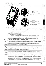
It is recommended that the internal EMC filter is kept in place unless there is a specific 
reason for removing it.
If the drive is to be used on an IT supply, then the filter must be removed.
The internal EMC filter reduces radio-frequency emissions into the mains supply. Where 
the motor cable is short, it permits the requirements of EN61800-3 to be met for the 
second environment.
For longer motor cables, the filter continues to provide a useful reduction in emission 
level, and when used with any length of shielded cable up to the limit for the drive, it is 
unlikely that nearby industrial equipment will be disturbed. It is recommended that the 
filter be used in all applications unless the ground leakage current is unacceptable or 
the above conditions are true.

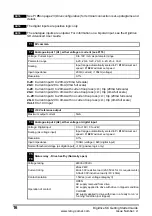
The above leakage currents are just the leakage currents of the drive with the internal EMC 
filter connected and do not take into account any leakage currents of the motor or motor cable.

NOTE

In both cases, there is an internal voltage surge suppression device connected to 
ground. Under normal circumstances, this carries negligible current.

NOTE

When the internal EMC filter is fitted, the leakage current is high. In this case, a 
permanent fixed ground connection must be provided using two independent conductors 
each with a cross-section equal to or exceeding that of the supply conductors. The drive 
is provided with two ground terminals to facilitate this. The purpose is to prevent a safety 
hazard occurring if a connection is lost.

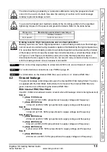
WARNING

Summary of Contents for DIGIDRIVE SK

Page 1: ...reference input A1 10V reference output Local voltage speed reference input A2 B1 B2 B3 B4 B5 B6 B7 24V output Drive Enable Reset USA Not stop Run Forward USA Run Run Reverse USA Jog Local A2 Remote...

Page 2: ...ntal impacts of its manufacturing operations and of its products throughout their life cycle To this end we operate an Environmental Management System EMS which is certified to the International Stand...

Page 3: ...trol terminals I O specification 15 5 Keypad and Display 18 5 1 Programming keys 18 5 2 Control keys 18 5 3 Selecting and changing parameters 19 5 4 Saving parameters 20 5 5 Parameter access 20 5 6 Se...

Page 4: ...4 Digidrive SK Getting Started Guide www leroy somer com Issue Number d Notes...

Page 5: ...personnel They do not isolate dangerous voltages from the output of the drive or from any external option unit The supply must be disconnected by an approved electrical isolation device before gainin...

Page 6: ...uction motors are designed for single speed operation If it is intended to use the capability of a drive to run a motor at speeds above its designed maximum it is strongly recommended that the manufac...

Page 7: ...t the capacitors may fail to discharge or be prevented from being discharged by a voltage applied to the output terminals If the drive has failed in a manner that causes the display to go blank immedi...

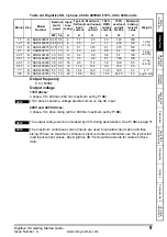
Page 8: ...g 3 0 Ib 2ML B SKB1100110 1 1 1 5 32 24 0 5 2 7 8 28 Model Size CT reference Nominal motor power Input fuse rating Typical full load input current 100 RMS output current 150 overload current for 60s M...

Page 9: ...3400037 0 37 0 5 6 1 7 2 5 1 3 1 95 100 1 2 kg 2 7 Ib 1 2T B SKB3400055 0 55 0 75 6 2 5 3 1 1 7 2 55 100 1 5T B SKB3400075 0 75 1 0 6 3 1 3 75 2 1 3 15 100 2T B SKB3400110 1 1 1 5 6 4 0 4 6 2 8 4 2 10...

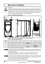
Page 10: ...C D E F G H I mm in mm in mm in mm in mm in mm in mm in mm in mm in A 140 5 51 154 6 06 11 0 43 64 2 52 75 2 95 145 5 71 104 4 09 143 5 63 B 190 7 48 205 8 07 10 9 0 43 65 9 2 6 85 3 35 77 3 0 156 6...

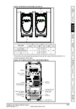
Page 11: ...This is the minimum spacing between drives at the base of the drive where it is mounted against a back plate Figure 3 3 Features of the drive size B illustrated Drive size A B C mm in mm in mm in A 10...

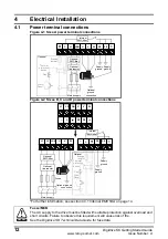
Page 12: ...upply Optional Thermal protection device Stop Start Reset PE Supply ground Internal EMC filter Optional EMC filter Optional ground connection Supply ground Optional EMC filter Optional line reactor Fu...

Page 13: ...C at 230V 50Hz proportional to supply voltage and frequency The drive must be grounded by a conductor sufficient to carry the prospective fault current in the event of a fault See also the warning in...

Page 14: ...mains supply Where the motor cable is short it permits the requirements of EN61800 3 to be met for the second environment For longer motor cables the filter continues to provide a useful reduction in...

Page 15: ...tended EMC filter disconnected A The control circuits are isolated from the power circuits in the drive by basic insulation single insulation only The installer must ensure that the external control c...

Page 16: ...V mA as parameter range Parameter range 4 20 20 4 0 20 20 0 4 20 20 4 VoLt Scaling Input range automatically scaled to Pr 01 Minimum set speed Pr 02 Maximum set speed Input impedance 200 current 100k...

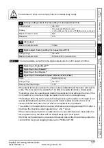
Page 17: ...trip where they become edge triggered See and above If the enable and run forward or enable and run reverse terminals are closed when the drive is powered up the drive will run straight away up to a...

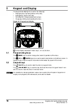
Page 18: ...d 5 1 Programming keys The MODE key is used to change the mode of operation of the drive The UP and DOWN keys are used to select parameters and edit their values In keypad mode they are used to increa...

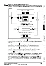
Page 19: ...and display flashes the value in the parameter being shown in the left hand display Pressing the MODE key in parameter edit mode will return the drive to the parameter view mode If the MODE key is pre...

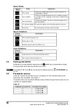
Page 20: ...he output bridge is inactive Drive inhibited The drive is inhibited because there is no enable command or a coast to stop is in progress or the drive is inhibited during a trip reset Drive has tripped...

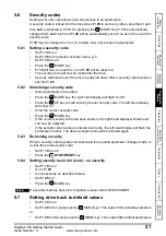
Page 21: ...er a security code has been set into Pr 25 5 6 2 Unlocking a security code Select parameter to be edited Press the MODE key the right hand display will flash CodE Press the UP key to start entering th...

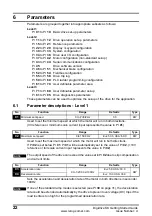
Page 22: ...1 Parameter descriptions Level 1 Used to set the minimum speed at which the motor will run in both directions 0V reference or minimum scale current input represents the value in Pr 01 Used to set the...

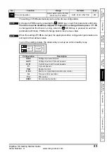
Page 23: ...o Pr 05 is set by pressing the MODE key on exit from parameter edit mode The drive must be disabled stopped or tripped for a change to take place If Pr 05 is changed while the drive is running when th...

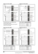
Page 24: ...0V Eur Analogue output motor speed Digital output zero speed Reference select Reference select 10k 2kmin T1 T2 T3 T4 B1 B2 B3 B4 B5 B6 B7 T4 B7 Reference selected 0 0 A1 0 1 Preset 2 1 0 Preset 3 1 1...

Page 25: ...verse V _ 24V 0V Eur Analogue output motor speed Digital output zero speed Not used Not used Not used Not used T1 T2 T3 T4 B1 B2 B3 B4 B5 B6 B7 0V 10V reference output 24V output Drive Enable Reset US...

Page 26: ...maximum speed Pr 02 20 WARNING 95 94 T4 T2 x 1 0 1 63 Invert 61 P Gain 62 I Gain PID reference input PID feedback input B7 PID enable Drive healthy 64 PID high limit 65 PID low limit 66 81 Drive refe...

Page 27: ...to 95 can be accessed LoC Used to lock a security code in the drive See section 5 6 Security codes on page 21 for further details No Function Range Defaults Type 06 Motor rated current 0 to Drive rat...

Page 28: ...e Yes 2 Enable Run Forward Reverse No 3 Stop Run Forward Reverse Yes 4 Stop Run Jog Yes 5 User programmable Run Forward Run Reverse No 6 User Programmable User Programmable User Programmable User Prog...

Page 29: ...SP Motor speed in rpm Cd Machine speed in customer defined units See Pr 24 Multiplying factor on motor speed rpm to give customer defined units Used to set up a user security code See section 5 6 Sec...

Page 30: ...by using Prog mode otherwise the drive will trip on C Acc at power up When boot mode is enabled it is impossible to return to rEAd or Prog mode To disable this mode please get in touch with your usual...

Page 31: ...age to frequency ratio constant torque standard load On Voltage to frequency ratio dependant on load current dynamic variable torque load This gives a higher motor efficiency 0 Disabled 1 Detect posit...

Page 32: ...ctionality of terminal B7 as set up with Pr 05 drive configuration will be disabled When setting to th press mode four times Analogue reference 2 will no longer be selected as the speed reference NOTE...

Page 33: ...Type 38 Autotune 0 to 2 0 RW When a rotating autotune is selected the drive will accelerate the motor up to 2 3 maximum speed in Pr 02 WARNING The motor must be at a standstill before a non rotating...

Page 34: ...rive has been commanded to stop the brake is applied immediately Defines the time between the frequency and load condition being met and the brake being released The ramp is held during this time Defi...

Page 35: ...hreshold 46 47 _ Motor frequency Brake release frequency Brake apply frequency 48 49 _ _ Reference enabled Latch Drive active In Out Reset Pre brake release delay 50 Post brake release delay 51 Brake...

Page 36: ...no PLC ladder program 1 LogicStick is fitted PLC ladder program is installed but stopped 2 LogicStick is fitted PLC ladder program is installed and running 3 LogicStick is not fitted Pr 61 to Pr 70 a...

Page 37: ...lowing read only RO parameters can be used as an aid to fault diagnosis on the drive See Figure 8 1 Diagnostics logic diagram on page 44 No Function Range Defaults Type 71 to Pr 61 to Pr 70 set up 0 t...

Page 38: ...e input A1 10V reference output Local voltage speed reference input A2 24V output Drive Enable Reset Run Forward Run Reverse Local A2 Remote A1 speed reference select 10k 2kmin Eur USA Analogue output...

Page 39: ...ot a standard 50 60Hz motor set Pr 39 accordingly Ready to autotune Enable and run the drive Close The Enable and Run Forward or Run Reverse signals Autotune The Digidrive SK will carry out a non rota...

Page 40: ...required control terminal connections 0V 10V reference output 24V output Drive Enable Reset Forward Reverse Analogue output motor speed Digital output zero speed Not used Not used Not used Not used T1...

Page 41: ...tor in Pr 09 If the motor is not a standard 50 60Hz motor set Pr 39 accordingly Ready to autotune Enable and run the drive Close The enable signal Press the START key Autotune The Digidrive SK will ca...

Page 42: ...d on drives heatsink Heatsink temperature exceeds allowable maximum th Motor thermistor trip Excessive motor temperature O Ld1 User 24V or digital output overload Excessive load or short circuit on 24...

Page 43: ...rring parameters SmartStick or when changing the default settings The drive is running or enabled Repeat the procedure with the drive locked Trip code Condition Possible cause Drive voltage rating UV...

Page 44: ...84 DC bus voltage 42 41 40 39 38 37 32 09 08 07 06 Motor rated current Motor rated speed Motor rated voltage Motor power factor Dynamic V to f select Switching frequency Autotune Motor rated frequency...

Page 45: ...eNet SM CANopen SM INTERBUS SM Ethernet SM Keypad Plus Remote panel mounting LCD multilingual text keypad display to IP54 NEMA 12 with additional help key SK Keypad Remote Remote panel mounting LED di...

Page 46: ...all of the drive s advanced parameters and also on the serial communications Furthermore it gives set up examples for the drive Option Module User Guides Installation Sheets These guides provide detai...

Page 47: ...13 Not used 14 15 Jog reference Hz 1 5 16 Analogue input 1 mode mA 4 20 17 Enable negative preset speeds OFF 18 Preset speed 1 Hz 0 0 19 Preset speed 2 Hz 0 0 20 Preset speed 3 Hz 0 0 21 Preset speed...

Page 48: ...67 Configurable parameter 7 68 Configurable parameter 8 69 Configurable parameter 9 70 Configurable parameter 10 Level 3 parameters 71 Pr 61 set up parameter 72 Pr 62 set up parameter 73 Pr 63 set up...

Page 49: ...ast acting fuses e g Bussman Limitron KTK series Gould Amp Trap ATM series or equivalent are used in the AC supply 11 2 AC supply specification The drive is suitable for use in a circuit capable of de...

Page 50: ...2kmin 24V 0V Pr 29 Eur Analogue output motor speed Digital output zero speed T5 T6 OK Fault T1 T2 T3 T4 0V Remote current speed reference input A1 10V reference output Local voltage speed reference i...

Reviews: