Digidrive SK Getting Started Guide
11
Issue Number: d
www.leroy-somer.com
Sa
fe
Rat
in
Mec
El
Ke
yp
Pa
ra
Qu
ick S
D
O
P
UL L
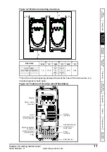
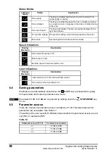
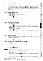
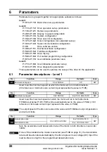
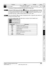
Figure 3-2 Minimum mounting clearances
*This is the minimum spacing between drives at the base of the drive where it is
mounted against a back plate.
Figure 3-3 Features of the drive (size B illustrated)
Drive size
A
B
C
mm
in
mm
in
mm
in
A
10
0.39
0
0
100
3.94
B (
≤
0.75kW)
10*
0.39*
B (
≥
1.1kW) or B (110V)
0
0
C
50*
1.97*
D
0
0
A
A
B
C
C
Display
Smart / Logic
Stick slot
Power
terminals
Control
terminals
Serial
communications
port connector
EMC filter tab
Solutions Module
connector
protective cover
(size B and C
only)
Solutions Module
slot (size B, C
and D only)

