Leonton PG2-0601-SFP Series User Manual Download Page 5

Overview 

This series is rated IP30 and installation by DIN Rail. Each unit of this industrial gigabit unmanaged 
Ethernet switch series has 5*10/100/1000Tx with 4*IEEE 802.3at compliant ports (30W/port) and 
1 dual  rate  (100/1000)  SFP  slots,  suitable for  applications that  require high bandwidth  and long 
distance communication.


In  order  to  prevent  unregulated  voltage,  this  series  provides  high  EFT  and  ESD  protection.  This 
also allows it to function in harsh environments, as well as support power redundancy with a dual 
power  input  design  with  reverse  polarity  protection.  The  built-in  relay  warning  function  alerts 
users about occurring power failures.


With  one  model  having  an  operating  temperature  of  -10°C  ~  65°C,  and  another  with  a  wide 
operating  temperature  of  -40°C  ~  75°C,  this  series  is  designed  to  meet  any  needs  for  industrial 
automation application and harsh environments.


Key Features 

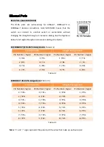
Interface & Performance


All Copper ports support auto MDI/MDI-X function


Embedded 4*10/100/1000Tx (PSE 30W/Port) + 1*10/100/1000Tx and 1*100/1000 SFP Slots


Store-and-forward switching architecture


8K MAC Address Table


Supports 10Kbytes Jumbo Frame


1Mbits memory buffer


Power Input


Redundant power DC 48-55V with connective 1*6-pin removable terminal block


Max. current 10A


Max. PoE output: 120W


Relay Contact: 24VDC, 1A resistive


Certification 


CE/FCC 


UL 61010-1 


UL 61010-2-201 


ISA 12.12.01 

Operating Temperature


Standard operating temperature model: -10°C ~ 65°C


Extended operating temperature model (–T): -40°C ~ 75°C


Case/Installation


IP30 protection


Installation in pollution degree to environment


DIN-Rail and Wall mount design


Summary of Contents for PG2-0601-SFP Series

Page 1: ...Leonton PG2 0601 SFP Series PG2 0601 SFP PG2 0601 SFP T User Manual Version 1 0...

Page 2: ...t not limited to the implied warranties of merchantability and fitness for a particular purpose Leonton Technologies Co Ltd may make improvements and or changes to the product and or specifications of...

Page 3: ...the equipment off and on the user is encouraged to try to correct the interference by one or more of the following measures Reorient or relocate the receiving antenna Increase the separation between t...

Page 4: ...sical Dimensions 3 Front Panel 4 Top View 4 LED Indicators 5 Ethernet Ports 6 Cabling 7 Wiring the Power Inputs 9 Wiring the Fault Alarm Contact 11 DIP Switch Settings 12 Mounting Installation 13 DIN...

Page 5: ...10 C 65 C and another with a wide operating temperature of 40 C 75 C this series is designed to meet any needs for industrial automation application and harsh environments Key Features Interface Perfo...

Page 6: ...tion If the DC voltage is supplied by an external circuit please use a protection device on the power supply input Supply by UL Listed industrial use power The industrial Ethernet switch s hardware sp...

Page 7: ...3 Hardware Description Physical Dimensions Figure 2 1 below shows the physical dimensions of PG2 0601 SFP series W x H x D is 30mm x 142mm x 99mm Figure 2 1 PG2 0601 SFP Series Physical Dimensions...

Page 8: ...is shown below in Figure 2 2 Figure 2 2 The Front Panel of PG2 0601 SFP Series Top View Figure 2 3 below shows the top panel of the PG2 0601 SFP series switch that is equipped with one 6 pin removal t...

Page 9: ...s inactive Fault Red On Power input 1 or 2 is inactive Off Power input 1 and 2 are both functional SFP Port LINK ACT Green On Connected to network Flashing Networking is active Off Not connected to ne...

Page 10: ...aight Through Cable Pin Number Signal Pin Number Signal Pin Number Signal Pin Number Signal 1 RX 3 TX 1 RX 1 TX 2 RX 6 TX 2 RX 2 TX 3 TX 1 RX 3 TX 3 RX 6 TX 2 RX 6 TX 6 RX Table 2 2 1000BASE T RJ 45 P...

Page 11: ...t optical transceiver used in optical communications for both telecommunication and data communication applications To connect the transceiver and LC cable please follow below steps Step 1 Insert the...

Page 12: ...ure 2 11 Figure 2 11 LC Connector to the Transceiver To remove the LC connector from the transceiver please follow the steps shown below Step 1 Press the upper side of the LC connector from the transc...

Page 13: ...13 Figure 2 13 Pull Out from the SFP Module Wiring the Power Inputs Please follow the below steps to insert the power wire Step 1 Insert the positive and negative wires into the PWR1 V1 V1 and PWR2 V...

Page 14: ...crews to prevent the wires from loosening as shown below in Figure 2 15 Figure 2 15 Power Terminal Block Note Only use copper conductors 60 75 C tighten to 5 lbs The wire gauge for the terminal block...

Page 15: ...luding power failure or port link failure managed industrial switch only and form a normally open circuit An application example for the fault alarm contact is shown below in Figure 2 16 Figure 2 16 W...

Page 16: ...IP Switch Settings The following describes the DIP switch settings DIP Switch ON OFF 1 Enable Energy Efficient Ethernet Disable Energy Efficient Ethernet 2 Set SFP speed to 100Mbps Set SFP speed to 1G...

Page 17: ...ure 3 1 The Rear Side of the Switch and DIN Rail Bracket Follow the steps below to learn how to hang the industrial Ethernet switch Step 1 Use the screws to install the DIN Rail bracket on the rear si...

Page 18: ...ull down the bracket on to the rail as shown below in Figure 3 3 Figure 3 3 Stable the Switch on DIN Rail Step 5 Check if the bracket is mounted tightly on the rail Step 6 To remove the industrial Eth...

Page 19: ...ottom of the industrial Ethernet switch Step 3 Use the screws to screw the wall mounting bracket on the industrial Ethernet switch Step 4 Use the hook holes at the corners of the wall mounting bracket...

Page 20: ...o the Mounting Installation section Step 4 Power on the industrial Ethernet switch and then the power LED light will turn on If you need help on how to wire power please refer to the Wiring the Power...

Page 21: ...assist in identifying problems the switch can be easily monitored with the LED indicators which help to identity if any problems exist Please refer to the LED Indicators section for LED light indicat...

Reviews: