Leonton
MET2-0201-M Series
(MET2-0201-M / MET2-0201-M-T)
User Manual
Version 1.0
Page 1: ...Leonton MET2 0201 M Series MET2 0201 M MET2 0201 M T User Manual Version 1 0...
Page 2: ...t not limited to the implied warranties of merchantability and fitness for a particular purpose Leonton Technologies Co Ltd may make improvements and or changes to the product and or specifications of...
Page 3: ...the equipment off and on the user is encouraged to try to correct the interference by one or more of the following measures Reorient or relocate the receiving antenna Increase the separation between t...
Page 4: ...el 4 Top View 4 LED Indicators 5 DIP Switch Setting 6 Ethernet Ports 7 Fiber Port 8 Cabling 8 Wiring the Power Inputs 9 Wiring the Fault Alarm Contact 10 Grounding Note 10 Mounting Installation 11 DIN...
Page 5: ...industrial automation application and harsh environments Key Features Interface Performance Copper port support auto MDI MDI X function Embedded 1 10 100Tx Fast Ethernet and 1 100Fx SC ST type connec...
Page 6: ...a protection device on the power supply input Supply by UL Listed industrial use power The industrial Media Converter s hardware specs ports cabling information and wiring installation will be describ...
Page 7: ...3 Hardware Description Physical Dimensions Figure 2 1 below shows the physical dimensions of MET2 0201 M series W x H x D is 26mm x 95mm x 75mm Figure 2 1 MET2 0201 M Series Physical Dimensions...
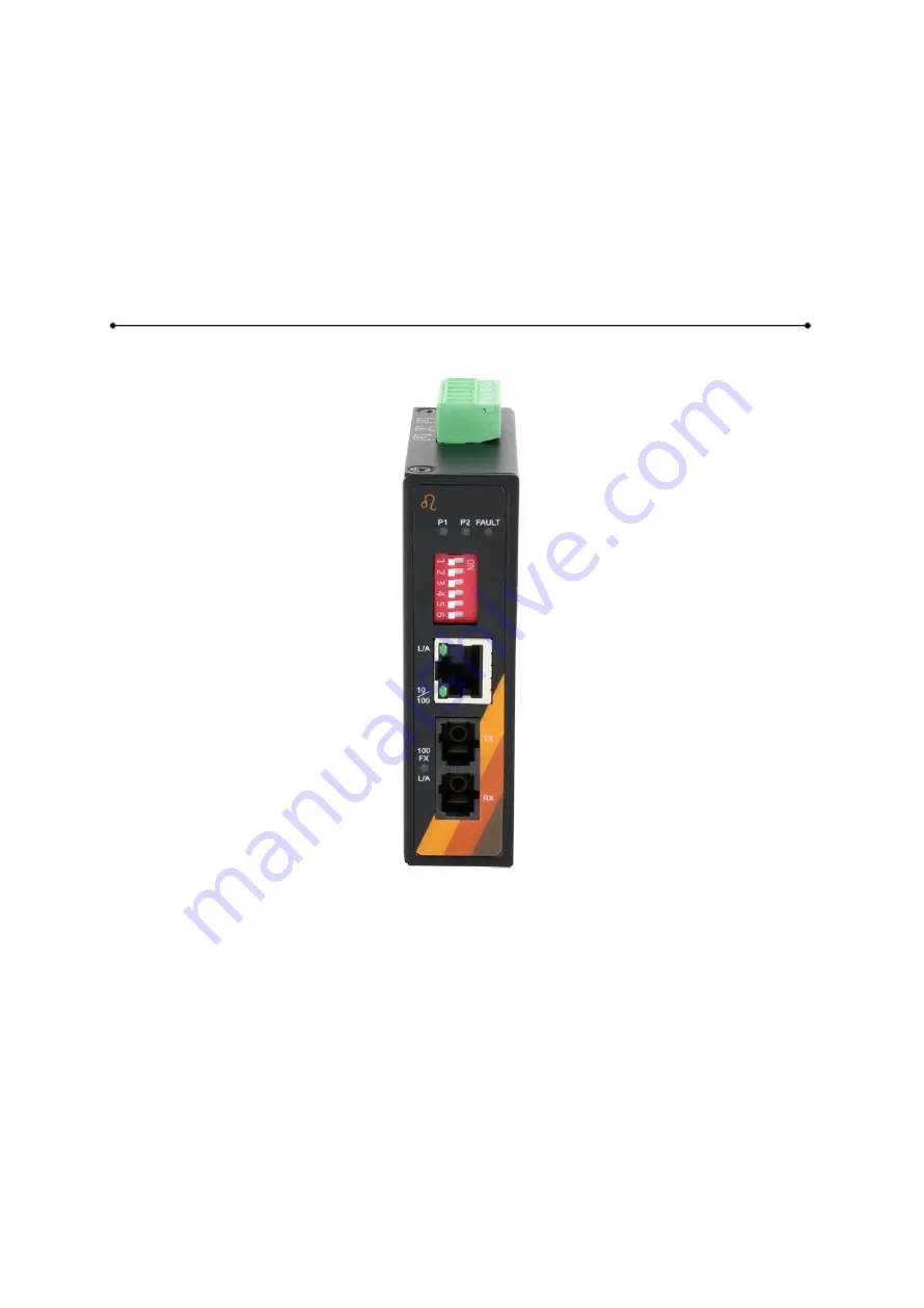
Page 8: ...low in Figure 2 2 Figure 2 2 The Front Panel of MET2 0201 M Series Top View Figure 2 3 below shows the top panel of the MET2 0201 M series Media Converter that is equipped with one 6 pin removal termi...
Page 9: ...Fault Red On Power input 1 or 2 is inactive or Port link failed Off Power input 1 and 2 are both functional and Port link correct LAN Port LINK ACT Green On Connected to network 10 100Mbps Flashing N...
Page 10: ...mode default DIP Switch 3 ON Set Fiber Port at Half Duplex OFF Set Fiber Port at Full Duplex default DIP Switch 4 ON Disable Auto negotiation on Copper Port OFF Enable Auto negotiation on Copper Port...
Page 11: ...raight Through Cable Pin Number Signal Pin Number Signal Pin Number Signal Pin Number Signal 1 RX 3 TX 1 RX 1 TX 2 RX 6 TX 2 RX 2 TX 3 TX 1 RX 3 TX 3 RX 6 TX 2 RX 6 TX 6 RX Table 2 6 1000BASE T RJ 45...
Page 12: ...is a Class 1 Laser LED product that complies with IEC 60825 1 Don t stare into the Laser LED Beam Cabling Use the four twisted pair category 5e or the above cabling for RJ 45 port connections The cabl...
Page 13: ...on the terminal block connector as shown below in Figure 2 9 Figure 2 9 Power Terminal Block Step 2 Tighten the wire clamp screws to prevent the wires from loosening as shown below in Figure 2 10 Fig...
Page 14: ...the Fault Alarm Contact Caution The wire gauge for the terminal block should range between 12 24 AWG If only using one power source jumper Pin 1 to Pin 5 and Pin 2 to Pin 6 to eliminate power fault a...
Page 15: ...and DIN Rail Bracket Follow the steps below to learn how to hang the industrial Media Converter Step 1 Use the screws to install the DIN Rail bracket on the rear side of the industrial Media Converte...
Page 16: ...ull down the bracket on to the rail as shown below in Figure 3 3 Figure 3 3 Stable the Media Converter on DIN Rail Step 5 Check if the bracket is mounted tightly on the rail Step 6 To remove the indus...
Page 17: ...wall mounting brackets on the top and bottom of the industrial Media Converter Step 3 Use the screws to screw the wall mounting bracket on the industrial Media Converter Caution The torque for tighte...
Page 18: ...14 Below in Figure 3 5 are the dimensions of the wall mounting bracket Figure 3 5 Wall Mounting Bracket Dimensions...
Page 19: ...he power LED light will turn on If you need help on how to wire power please refer to the Wiring the Power Inputs section Please refer to the LED Indicators section for LED light indication Step 5 Pre...
Page 20: ...l as other cables Be careful when handling them so as to not trip over Do not under any circumstance insert foreign objects of any kind into the heat dissipation holes located in the different faces o...
Page 21: ...n identifying problems the Media Converter can be easily monitored with the LED indicators which help to identity if any problems exist Please refer to the LED Indicators section for LED light indicat...