l
IMS94S-mv1
16
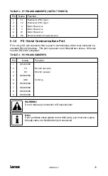
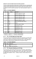
5.1.3 P3 - Controller Interface
P3 is a 25-pin DB connector for interfacing to front-end controllers. It is strongly
recommended that you use OEM cables to aid in satisfying CE requirements. Contact
your SimpleServo representative for assistance.
TABLE 5 - P3 PIN ASSIGNMENTS
Pin
Name
Function
(1)
1
EA+
Encoder Channel A+ Output
2
EA-
Encoder Channel A- Output
3
EB+
Encoder Channel B+ Output
4
EB-
Encoder Channel B- Output
5
EZ+
Encoder Channel Z+ Output
6
EZ-
Encoder Channel Z- Output
7
GND
Drive Common
8
SHLD
Shield
9
+5V
+5V
10
IN2
Digital Input #2 (Programmable)
11
MA+/Step+
Master Encoder A+ / Step input+
(2)
12
MA-/Step-
Master Encoder A- / Step input-
(2)
13
MB+/Dir+
Master Encoder B+ / Direction input +
14
MB-/Dir-Master
Encoder B- / Direction input
15
OUT1-C
Programmable output #1 Collector
16
OUT1-E
Programmable output #1 Emitter
17
IN1
Digital Input #1 (Enable)
(3)
18
IN_COM
Digital Input Common
19
OUT2-C
Programmable output #2 Collector
20
OUT2-E
Programmable output #2 Emitter
21
AO
Programmable analog /- 10V
22
GND
Drive logic common
23
AIN+
Positive (+) of Analog signal input
24
AIN -
Negative (-) of Analog signal input
25
AG
Reference Signal Ground/Analog Shield
(1)
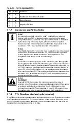
See Note 1, Section 5.1.7 - Connector and Wiring Notes
(2)
See Note 2, Section 5.1.7 - Connector and Wiring Notes
(3)
See Note 3, Section 5.1.7 - Connector and Wiring Notes
Summary of Contents for SimpleServo 94
Page 1: ...MODEL 94 USERS MANUAL IMS94S mv1 ...
Page 12: ...l IMS94S mv1 10 3 2 Clearance for Cooling Air Circulation ...
Page 56: ...l IMS94S mv1 54 ...
Page 57: ...IMS94S mv1 l 55 ...
Page 58: ...l IMS94S mv1 56 ...
Page 59: ...IMS94S mv1 l 57 ...
Page 60: ...l IMS94S mv1 58 ...
Page 61: ...IMS94S mv1 l 59 ...
Page 62: ...l IMS94S mv1 60 ...
Page 63: ...IMS94S mv1 l 61 ...
Page 64: ...l IMS94S mv1 62 ...
Page 65: ...IMS94S mv1 l 63 ...


