


15
Parameter reference
15.2
Parameter list
1070
Lenze · 8400 HighLine · Reference manual · DMS 12.0 EN · 06/2017 · TD23
_ _ _ _ _ _ _ _ _ _ _ _ _ _ _ _ _ _ _ _ _ _ _ _ _ _ _ _ _ _ _ _ _ _ _ _ _ _ _ _ _ _ _ _ _ _ _ _ _ _ _ _ _ _ _ _ _ _ _ _ _ _ _ _
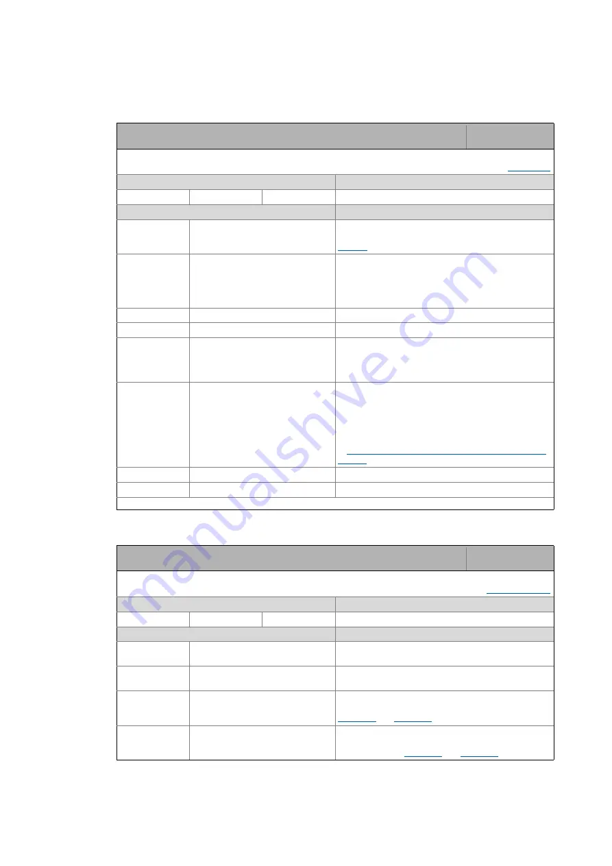
C01216
C01218
Parameter | Name:
C01216 | MCK: Positioning setting
Data type: UNSIGNED_8
Index: 23359
d
= 5B3F
h
From version 04.00.00
Setting range
(min. hex value | max. hex value)
Lenze setting
0x00
0xFF
0x01
(decimal: 1)
Value is bit-coded: (
= bit set)
Info
Bit 0
PosAbort at PosInit
1
≡
When a changeover to "positioning" mode is made,
ramping down at the rate of deceleration set in
for normal stopping is carried out.
Bit 1
PosExecute active at PosInit
1
≡
When a changeover is made to the "positioning"
mode, the specified profile is immediately executed if
the "MCK PosExecute" control bit has also been set. If the
MCK "PosExecute" control bit has not been set, the
setpoint is continued.
Bit 2
Reserved
Bit 3
Reserved
Bit 4
ProfilStart at PosInit
1
≡
When it is changed to the "Positioning" operating
mode, the defined profile is executed immediately
without the need to set the MCK control bit
"PosExecute".
Bit 5
Maximum jerk
1
≡
The maximum jerk is calculated based on the
acceleration and S-ramp time of the current profile and
the sequence profile. This is then used in an accelerated
drive for reducing the acceleration to 0 or for
acceleration of the sequence profile.
•
From version 14.00.00
Setting or activation of maximum jerk for traversing
Bit 6
Reserved
Bit 7
Reserved
Read access
Write access
CINH
PLC STOP
No transfer
COM
MOT
Parameter | Name:
C01218 | MCK: Position follower setting
Data type: UNSIGNED_8
Index: 23357
d
= 5B3D
h
Settings for "Position follower" mode
Setting range
(min. hex value | max. hex value)
Lenze setting
0x00
0xFF
0x0C
(decimal: 12)
Value is bit-coded: (
= bit set)
Info
Bit 0
Speed FF control.: nSpeedSetValue_a 1
≡
speed feedforward control value comes from main
setpoint
nSpeedSetValue_a
Bit 1
Speed FF control: nSpeedAddValue_v 1
≡
speed feedforward control value comes from additive
speed value
nSpeedAddValue_v
Bit 2
HW limit switch on
1
≡
Travel range monitoring via hardware limit switch is
active. The error response can be parameterised in
.
Bit 3
SW limit switch on
1
≡
Travel range monitoring via parameterised software
limit positions is active. The error response can be
parameterised in
.