


Lenze · I/O system 1000 · Reference Manual · DMS 5.0 EN · 09/2016 · TD17
72
4
Configuring the I/O system in the »PLC Designer«
4.3
Mapping the real station structure in the »PLC Designer«
_ _ _ _ _ _ _ _ _ _ _ _ _ _ _ _ _ _ _ _ _ _ _ _ _ _ _ _ _ _ _ _ _ _ _ _ _ _ _ _ _ _ _ _ _ _ _ _ _ _ _ _ _ _ _ _ _ _ _ _ _ _ _ _
4.3.5
Setting the cycle time for access to the I/O modules
In the Lenze Controller a central bus cycle task is selected, which is valid for the processing of all
fieldbuses and for the I/O modules connected via the backplane bus.
• This selection is a default setting and can be overwritten in the corresponding bus master nodes
(EtherCAT master, CANopen_Manager, I/O module coupler, ....).
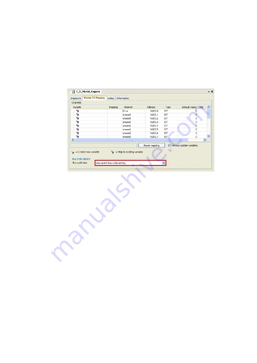
• If you require a shorter cycle time for the backplane bus than the one selected in the Lenze
Controller, you can select a faster task for I_O_Modul_Koppler on the
Module I/O Mapping
tab:
The following applies to I/O modules on the I_O_Modul_Koppler:
• At first, the »PLC Designer« defines a processing task for the PLC for generating the I/O image.
An individual bus cycle task can be defined for each individual module, within which the process
image for the module is then created.
• Altogether three different tasks for the I/O modules can be defined. The limitation to three
tasks is determined by the system on the basis of the backplane bus specification.
• The backplane bus controller uses two internal bus cycle groups for each task; one for input
signals and one for the outputs. A total of six groups is provided.